
Decorative article including a globe

a technology of decorative articles and globes, applied in the field of decorative articles, can solve the problems of increased production costs, increased production costs, and complexity, and achieve the effect of superior optical appearan

Active Publication Date: 2019-02-19
STOEWAHSE OLE
View PDF11 Cites 0 Cited by
  • Summary
  • Abstract
  • Description
  • Claims
  • Application Information

AI Technical Summary

Benefits of technology

The patent is about creating a decorative item that has a globe or similar part that is lit up and has a good optical appearance.

Problems solved by technology

The presence of the projection on the meridian and the presence of a stand results in the need for a larger amount of installation space relative to the size of the globe itself; the projection on the meridian is furthermore an additional component, which entails additional production costs and complexity.

Method used


Image

  • Decorative article including a globe
  • Decorative article including a globe

Examples


Embodiment Construction

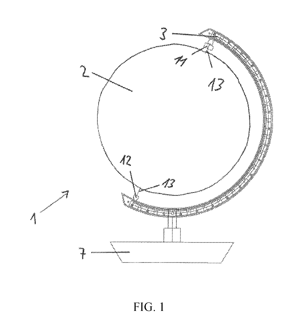
[0031]FIG. 1 shows a decorative article 1 comprising a globe 2 and a meridian 3 held on a stand 7. The globe 2 is in this case spherical and rotatably held on the meridian 3. However, other objects may also be held by the meridian 3. The stand 7 is not absolutely necessary to the invention if the globe 2 is suspended from the meridian 3 for example. In this case, the globe 2 is held on a spindle 13 which is received in a first bearing 11 and a second bearing 12. The bearings 11, 12 can allow rotation of the globe 2 or receive the globe 2 in a rotationally fixed manner. The first bearing 11, the second bearing 12 and / or the spindle 13 of the globe 2 may be designed to couple light into the globe 2. Alternatively, the globe 2 may guide light at least in part in order to allow said coupling-in of light. Light-guiding or light-scattering structures may be provided inside the globe 2 or on the surface thereof in order to make possible the targeted or omnidirectional illumination at least...


PUM


Abstract

The present invention relates to a decorative article comprising a globe held on a meridian, wherein the meridian is provided with at least one first light outlet element, the first light outlet element being optically coupled to at least one first lamp.

Description

CROSS REFERENCE TO A RELATED APPLICATION[0001]This application claims priority under 35 U.S.C. § 119(e) of German Patent Application No. DE 10 2017 203 829.2, filed Mar. 8, 2017, which is incorporated herein by reference in its entirety.FIELD OF THE INVENTION[0002]The present invention relates to a decorative article having the features of the preamble of claim 1.BACKGROUND OF THE INVENTION[0003]Illuminated globes to which a decorative value can be attributed are disclosed in CN 203013120 (U) and CN 203520754 (U). Both embodiments comprise the globe, a stand, which may be equipped with lamps, and a lamp, which is attached to a projection on a meridian. This design requires the projection to be additionally attached to or formed on the meridian in order to be able to attach the lamps thereto. The presence of the projection on the meridian and the presence of a stand results in the need for a larger amount of installation space relative to the size of the globe itself; the projection ...

Claims


Application Information

Patent Timeline
Patent Type & Authority Patents(United States)
IPC IPC(8): G09B27/08F21V8/00F21V33/00G09B27/06F21W121/00F21Y103/10F21Y103/33F21Y115/10
CPCG09B27/08F21V33/00F21V33/0004G02B6/0001G09B27/06F21Y2115/10F21W2121/00F21Y2103/10F21Y2103/33
Inventor STOEWAHSE, OLE
Owner STOEWAHSE OLE
Learn More