Supercharge Your Innovation With Domain-Expert AI Agents!

Motion detection system with flicker compensation

a motion detection and flicker compensation technology, applied in the field of motion detection, can solve the problems of moving flicker banding still occurring, power consumption becomes critical for lengthening the operation life of the motion detector, etc., and achieves the effect of low power consumption and motion detection sensitivity

Active Publication Date: 2022-02-15
HIMAX IMAGING LIMITED
View PDF1 Cites 0 Cited by
  • Summary
  • Abstract
  • Description
  • Claims
  • Application Information

AI Technical Summary

Benefits of technology

The present invention aims to provide a low-power motion detection system that can compensate for flicker and avoid false alarms while maintaining sensitivity and low power consumption. The technical effect of the invention is to improve the accuracy and reliability of motion detection in a cost-effective and efficient manner.

Problems solved by technology

Accordingly, power consumption becomes critical for lengthening operation lifetime of the motion detectors in a low-power motion detection system, which should stay always-on for monitoring.
Unfortunately, the flicker banding can be incorrectly detected as object motion as false alarm. FIG. 1B shows moving flicker banding (i.e., change of flicker banding) among multiple frames which may be incorrectly detected as object motion.
However, the moving flicker banding may still occur when the flicker frequency deviates.

Method used


Image

  • Motion detection system with flicker compensation
  • Motion detection system with flicker compensation
  • Motion detection system with flicker compensation

Examples


first embodiment

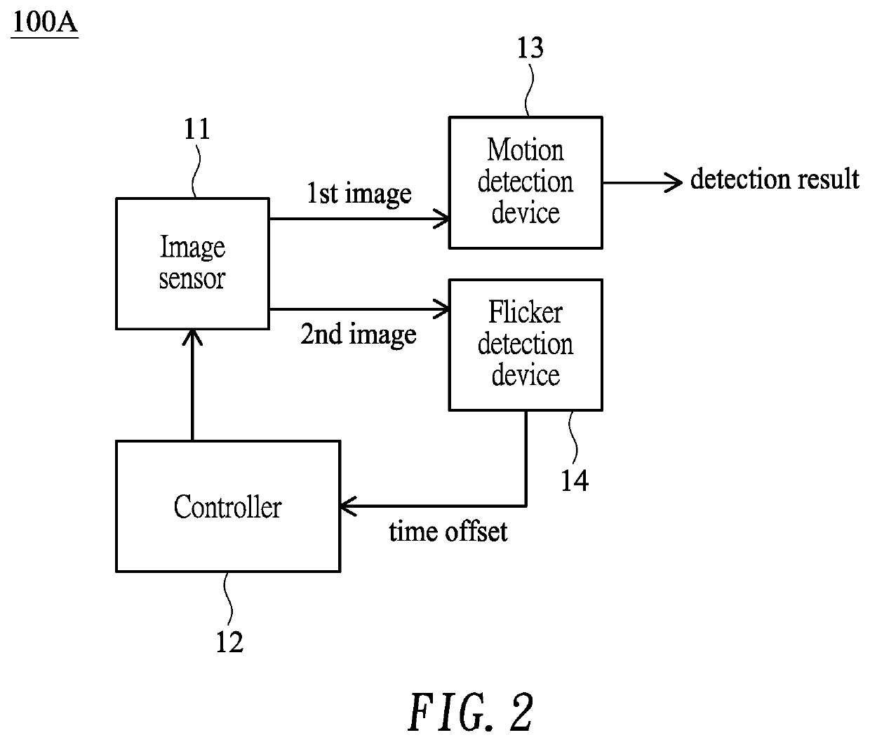
[0024]FIG. 2 shows a block diagram illustrating a motion detection system 100A with flicker compensation according to the present invention. Some blocks of the motion detection system 100A may be performed by hardware, software or their combinations (e.g., performed in a digital image processor).

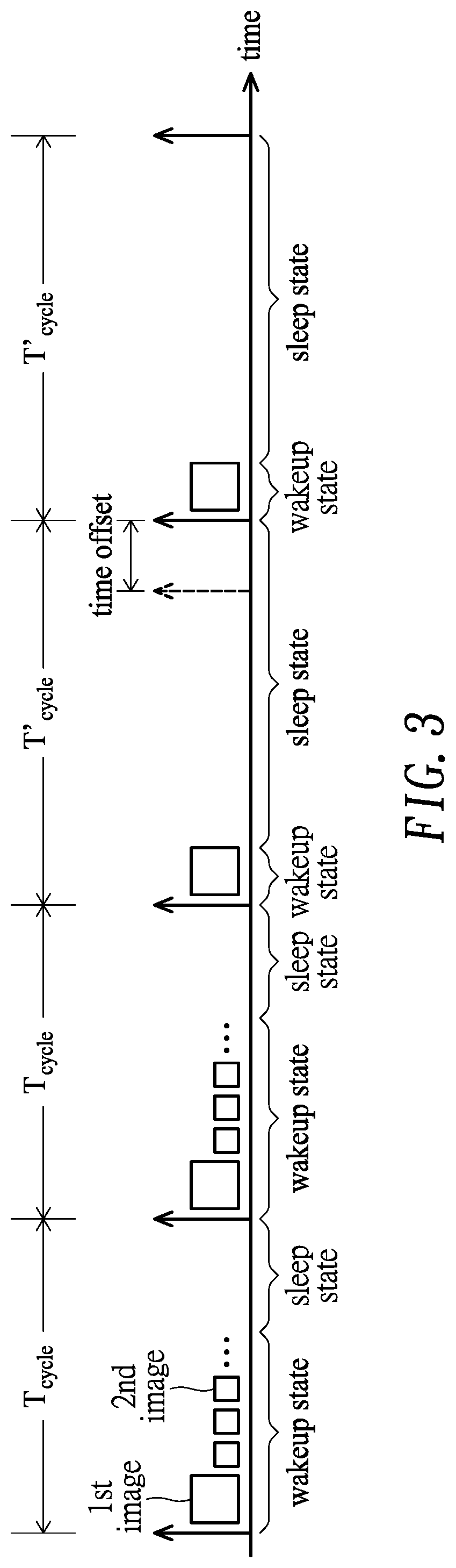
[0025]In the embodiment, the motion detection system 100A performs motion detection in an automatic wakeup and sleep mode, as exemplified in FIG. 3 showing a timing diagram composed of wakeup cycles Tcycle, each of which includes a wakeup state followed by a sleep state.

[0026]In the embodiment, the motion detection system 100A may include an image sensor 11, such as a pixel array, configured to capture a first image for motion detection or capture a second image for flicker detection, where the second image has a resolution lower than the first image. In the embodiment, second images are captured in at least two consecutive wakeup cycles Tcycle every predetermined number of wakeup cycles Tcy...

second embodiment

[0040]FIG. 7 shows a flow diagram illustrating a motion detection method 200B with flicker compensation according to the present invention. The motion detection method 200B as shown in FIG. 7 is similar to the motion detection method 100B of FIG. 4A except that step 103 of FIG. 4A is replaced with step 103B.

[0041]Specifically, in step 103B, an exposure setting (e.g., exposure time or gain) is obtained, and it is determined whether the exposure setting converges after an exposure setting change (indicating that there is an illumination change and the illumination flicker characteristics may also change correspondingly) and an exposure time is not equal to an integer multiple of an (illumination) flicker period. If decision of step 103B is positive, the flow goes to step 104 to capture second images. Otherwise, the flow goes to step 105 to reset a flicker count FCnt, and then goes back to step 101.


PUM


Abstract

A motion detection system with flicker compensation includes an image sensor that captures a first image for motion detection and a second image for flicker detection, the second image having a resolution lower than the first image; a controller that controls the image sensor to output either the first image or the second image; a motion detection device that receives first images and performs motion detection on the first images; and a flicker detection device that receives second images and performs flicker detection on the second images to generate a time offset, which is fed to the controller to update a wakeup cycle for coordinating the image sensor.

Description

BACKGROUND OF THE INVENTION1. Field of the Invention[0001]The present invention generally relates to motion detection, and more particularly to a motion detection system with flicker compensation.2. Description of Related Art[0002]Sensors, such as passive infrared sensors and image sensors, are commonly used as motion detectors for detecting object motion. For example, in a security camera system, motion detectors may trigger the security camera and capture high-resolution video when an object (e.g., person) is detected. In another example, motion detectors may activate light sources in an illumination system when human presence is detected.[0003]The image sensors are commonly installed at particular locations in order to fulfill the sensing function. For installation simplicity, the motion detectors are powered by battery instead of mains electricity. Accordingly, power consumption becomes critical for lengthening operation lifetime of the motion detectors in a low-power motion det...

Claims


Application Information

Patent Timeline
Patent Type & Authority Patents(United States)
IPC IPC(8): H04N5/235H04N5/232
CPCH04N5/2357H04N5/2351H04N5/2353H04N5/23232H04N23/6811H04N23/745H04N23/71H04N23/73H04N23/951
Inventor YANG, WEI-CHIEHCHEN, PO-CHANGCHEN, PO-FANG
Owner HIMAX IMAGING LIMITED
Features
  • R&D
  • Intellectual Property
  • Life Sciences
  • Materials
  • Tech Scout
  • Unparalleled Data Quality
  • Higher Quality Content
  • 60% Fewer Hallucinations
Learn More