Orthopaedic device

a technology of orthopaedic devices and couplings, applied in the field of orthopaedic devices, can solve the problems of shortening the limb, high failure rate, and extremely unstable fractures, and achieve the effect of reducing fractures

Active Publication Date: 2022-03-01
SOTA ORTHOPAEDICS
View PDF6 Cites 2 Cited by
  • Summary
  • Abstract
  • Description
  • Claims
  • Application Information

AI Technical Summary

Problems solved by technology

When the direction of a fracture is parallel to the femoral neck, the fracture can be extremely unstable.
A high rate of failure occurs if the fracture is treated with a sliding hip screw and a side plate.
Although sliding of the hip screw allows for bone compression and hopefully healing, it shortens the limb and causes abduction weakness.

Method used


Image

  • Orthopaedic device
  • Orthopaedic device
  • Orthopaedic device

Examples


Embodiment Construction

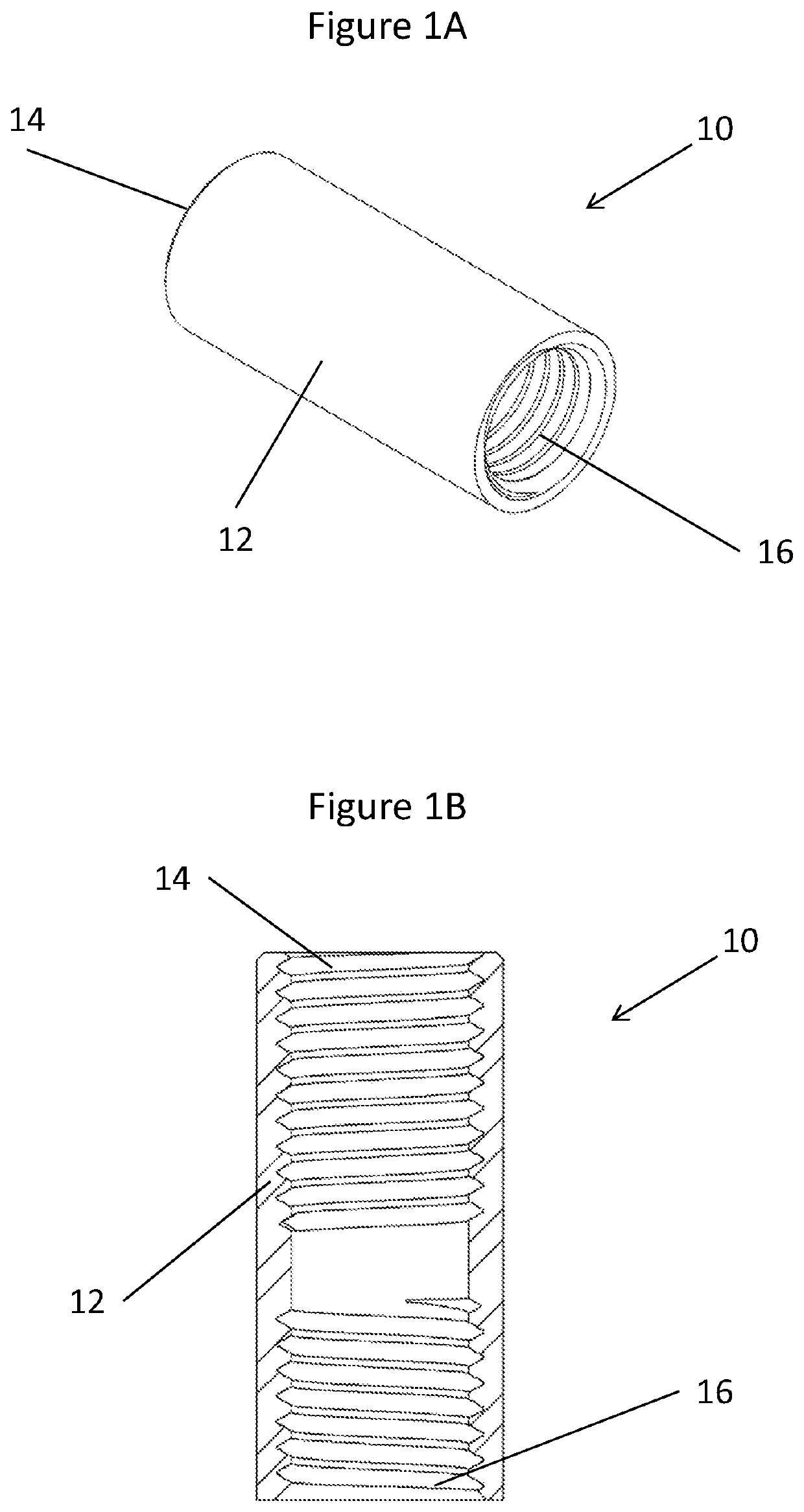
[0054]Referring now to FIGS. 1A and 1B of the drawings, there is shown a coupling 10 according to a first aspect of the invention. The coupling 10 comprises an annular body 12, which can be a substantially cylindrical shape having two opposing open ends, but can be of any cross-sectional shape. For example, the annular body 12 can be a substantially non-circular cylindrical shape to inhibit rotation of the annular body 12 relative to the external environment in which it is in contact, when in use.

[0055]The annular body 12 has an internal threaded surface comprising two sections 14, 16. The threaded sections 14, 16 are each helically threaded sections. The threads of the first section 14 are in reverse orientation to the threads of a second section 16. The two sections 14, 16 are spaced apart contiguous sections having a non-threaded section therebetween. The annular body 12 has opposing open ends, each shaped and dimensioned to receive a complimentary threaded shaft.

[0056]The inner ...


PUM


Abstract

This invention relates to a coupling for an orthopaedic device. Also disclosed in an orthopaedic device comprising a coupling of the invention and method for the use of the orthopaedic device. The orthopaedic device finds utility as a bolt apparatus for fixation of bones such as fractures of the femur, although it may be used in any suitable bone.

Description

FIELD OF THE INVENTION[0001]This invention relates to a coupling for an orthopaedic device. Also disclosed in an orthopaedic device comprising a coupling of the invention and method for the use of the orthopaedic device. The orthopaedic device finds utility as a bolt apparatus for fixation of bones such as fractures of the femur, although it may be used in any suitable bone.BACKGROUND TO THE INVENTION[0002]Bone fixation devices are well known and they find particular utility in the field of orthopaedic surgery, where they are used to fix a bone, which has sustained a fracture, across a fracture site. Generally, the type of fracture determines the type of surgery.[0003]Patients with femoral neck fractures are treated with pinning or hip arthroplasty, depending on the age of the patient and the presence and degree of displacement. Patients with intertrochanteric fractures are treated with a sliding hip screw or an intramedullary hip screw, depending on the stability and location of th...

Claims


Application Information

Patent Timeline
Patent Type & Authority Patents(United States)
IPC IPC(8): A61B17/84A61B17/86A61B17/74A61B17/00A61B17/72A61B17/56
CPCA61B17/844A61B17/863A61B17/7233A61B17/7258A61B17/7266A61B17/7275A61B17/742A61B17/8685A61B2017/00477A61B2017/00862A61B2017/564A61B2017/8655
Inventor THORNES, BRIANMCDONALD, ROSS
Owner SOTA ORTHOPAEDICS
Why Eureka
Try Eureka