Nail punching machine for driving in or pulling out rail spikes of a rail track
a technology for rail tracks and nail punching machines, which is applied in the direction of portable power-driven tools, manufacturing tools, and ways, can solve the problems of high exhaustion and discomfort of operators working with such nail punching machines, and achieve the effect of simple construction and high user comfor
- Summary
- Abstract
- Description
- Claims
- Application Information
AI Technical Summary
Benefits of technology
Problems solved by technology
Method used
Image
Examples
first embodiment
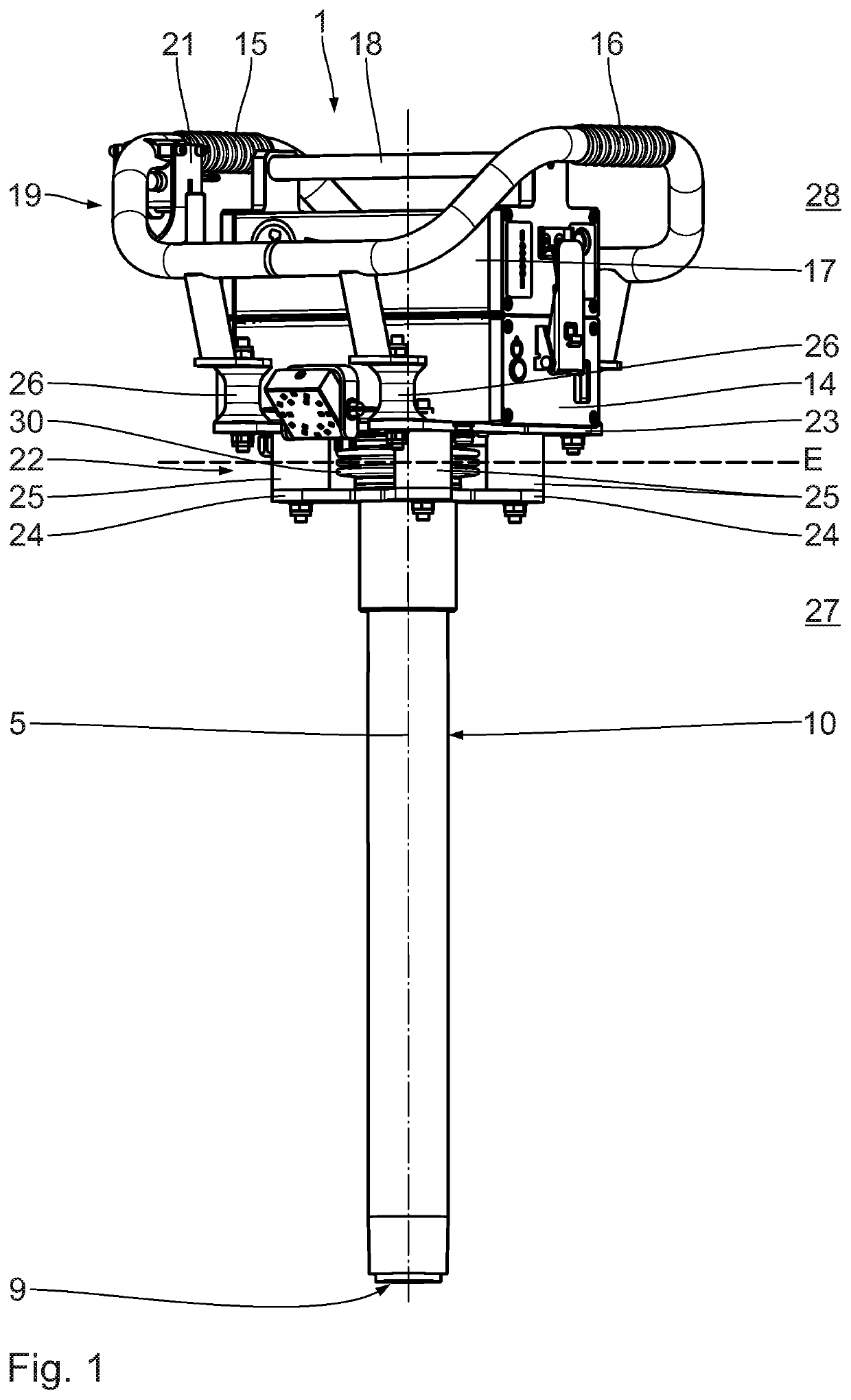
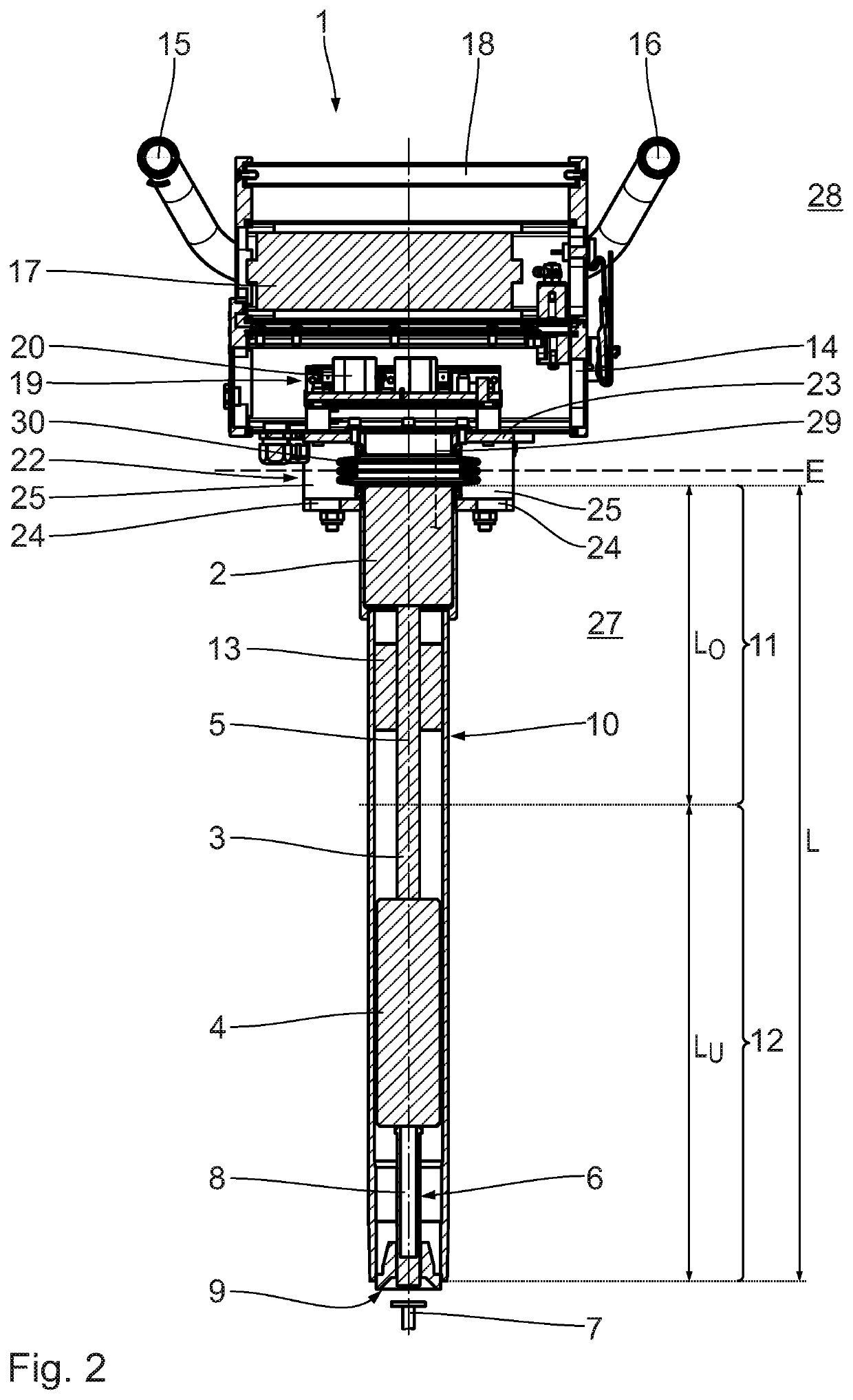
[0024]In the following, the invention is described with reference to FIGS. 1 and 2. An electrically drivable nail punching machine 1 has an electric drive motor 2, which is connected via a driving shaft 3 with a driving mechanism 4. The driving mechanism 4 is configured in the usual manner as an axial driving mechanism, which is displaceable exclusively in a linear manner in the direction of a rotation axis 5 of the drive motor 2.
[0025]The driving mechanism 4, for example, is configured as an axial striking mechanism. The driving mechanism 4 is known and common.
[0026]The driving mechanism 4 is exchangeably coupled with a tool 6. The tool 6 is configured as a hammer for driving in a rail spike 7. The tool 6 comprises a hammer shaft 8 and a hammer head 9. The tool 6 configured as a hammer is known and common. The nail punching machine 1 with the tool 6 configured as a hammer thus serves as a spike driver.
[0027]The electric drive motor 2, the driving shaft 3 and the driving mechanism 4...
second embodiment
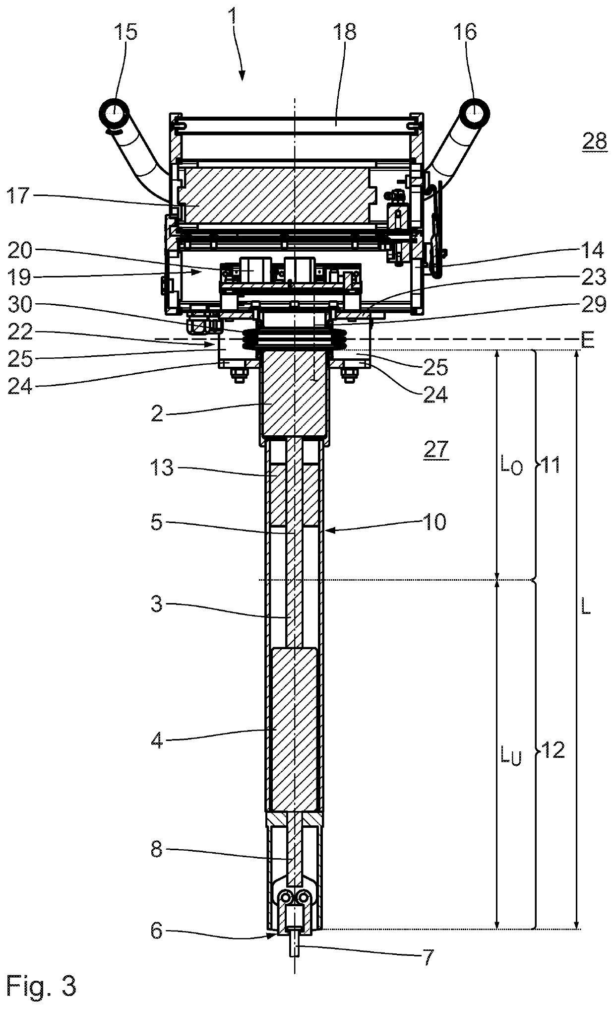
[0035]In the following, the invention is described with reference to FIG. 3. In contrast to the preceding embodiment, the tool 6 is configured as pliers for pulling out rail spikes 7. The nail punching machine 1, due to the configuration of the tool 6, thus serves as a spike puller. The tool 6 is exchangeably connected with the driving mechanism 4, with the result that the nail punching machine 1, via a tool change and the use of a tool 6 configured as a hammer, can also be used as a spike driver. For pulling out a rail spike 7, the pliers are drawn in the direction of the decoupling plane E by means of the driving mechanism 4 and the electric drive motor 2, with the result that the rail spike 7 to be pulled is pulled out of the tie and into the pipe 10. The operator, during this process, supports the nail punching machine 1 on the tie with the free end of the pipe 10. With regard to the further setup and the further functions, reference is made to the preceding embodiment.
third embodiment
[0036]In the following, the invention is described with reference to FIG. 4. In contrast to the preceding embodiments, the electric drive motor 2 is arranged in the lower section 12, i.e. outside the upper section 11 of the pipe 10. The electric drive motor 2 is directly connected with the driving mechanism 4, with the result that no additional driving shaft and no corresponding bearing are required. The nail punching machine 1 further on comprises a cooling device 31 with a cooler 32, a pump 33 and a coolant line 34. The cooler 32 and the pump 33 are arranged on the supporting frame 14 on the operating side 28. The coolant line 34 leads from the cooler 32 and the pump 33 through the decoupling plane E into the pipe 10 and to the drive motor 2 and the driving mechanism 4. By means of the pump 33, a coolant is pumped through the coolant line 34, with the result that heat produced by the drive motor 2 and the driving mechanism 4 is dissipated from the pipe 10 and conveyed to the coole...
PUM
 Abstract
Description
Claims
Application Information
 - R&D
- Intellectual Property
- Life Sciences
- Materials
- Tech Scout
- Unparalleled Data Quality
- Higher Quality Content
- 60% Fewer Hallucinations
Browse by: Latest US Patents, China's latest patents, Technical Efficacy Thesaurus, Application Domain, Technology Topic, Popular Technical Reports.
© 2025 PatSnap. All rights reserved.Legal|Privacy policy|Modern Slavery Act Transparency Statement|Sitemap|About US| Contact US: help@patsnap.com


