AI technical title is built by PatSnap AI team. It summarizes the technical point description of the patent document.
a steering device and steering angle technology, applied in the direction of electric steering, power driven steering, vehicle components, etc., can solve the problems of low rigidity of transmission path, difficult to precisely control the steering angle of the wheels, and difficulty in autonomous driving
Active Publication Date: 2022-04-05
TOYOTA JIDOSHA KK
View PDF7 Cites 0 Cited by
Summary
Abstract
Description
Claims
Application Information
AI Technical Summary
This helps you quickly interpret patents by identifying the three key elements:
Problems solved by technology
Method used
Benefits of technology
Benefits of technology
[0004]The present invention has been made to deal with the above-mentioned problem. That is, one object of the present invention is to provide a steering device of a ball-nut type for a vehicle, which is capable of precisely controlling tuning angles of steered wheels and can suitably be used in a cab over-engine vehicle and the like.
[0009]With this configuration, the swing member (center arm (26)) and the rod member (40A or 40B) cannot be displaced relative to each other in the right-and-left direction (that is, the drive direction of the rod member (40A or 40B) by the swing member (center arm (26)), but can be displaced relative to each other in the front-and-rear direction. Therefore, even when the movement of the rod member (40A or 40B) in the front-and-rear direction is restricted, the swing of the swing member (center arm (26)) can be transmitted to the rod member (40A or 40B). Moreover, with this configuration, the swing member (center arm (26)) and the rod member (40A or 40B) can be coupled so as to relatively move in the front-and-rear direction of the vehicle body (BD) without interposition of other coupling members between the swing member (center arm (26)) and the rod member (40A or 40B).
[0011]With this configuration, the swing member (center arm (26)) and the rod member (40A or 40B) can move relative to each other smoothly even when a relative direction between the swing member (center arm (26)) and the rod member (40A or 40B) changes due to a deformation of the vehicle body (BD) and the like. Moreover, with the configuration in which the coupling protrusion portion (26a) is elastically biased by the coupling-protrusion-portion biasing members (compression coil springs (403a and 403b)) to the middle position of the movable range in the length direction of the long hole (401), kickback transmitted from the rod member (40A or 40B) to the swing member (center arm (26)) can be reduced.
[0013]With this configuration, generation of noise can be prevented or suppressed when the rod member (40A or 40B) operates.
[0016]With this configuration, the rod member (40A or 40B) can directly be driven, and the movement amount of the rod member (40A or 40B) can thus highly precisely be controlled.
Problems solved by technology
However, in the related-art steering device configured to apply the force of the drive devices to the ball nuts, a large number of members such as the pitman arm, the drag link, the center arm, the rod members, and the tie rods are interposed between the drive devices and the steered wheels, with the result that the rigidity of a transmission path of the force is low.
Thus, for example, when the steered angles are controlled through use of the drive devices, steered angles are not uniquely determined with respect to control amounts (operation amounts) of the drive devices in some cases, and it is thus difficult to precisely control the steered angles of the wheels.
Therefore, there is a problem that it is not easy to perform autonomous driving, which requires precise control of steered angles, through use of the steering device.
Method used
Image
Click on the blue label to locate the original text in one second.
Reading with bidirectional positioning of images and text.
Examples
first embodiment
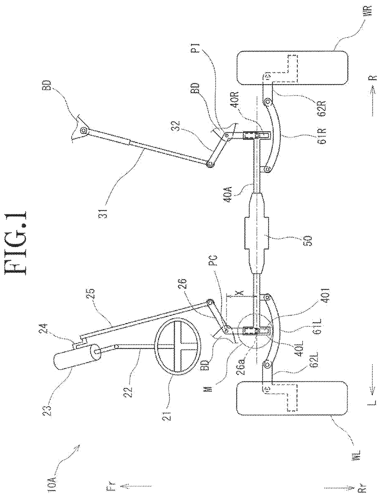
[0027]As illustrated in FIG. 1, a steering device 10A according to a first embodiment of the present invention includes a steering wheel 21, a steering shaft 22, a steering gear box 23, a pitman arm 24, a drag link 25, and a center arm 26. Moreover, the steering device 10A includes a damper 31 and an idler arm 32. Further, the steering device 10A includes a rod member 40A, a rod-member drive device 50, a right tie rod 61R, a left tie rod 61L, a right knuckle arm 62R, and a left knuckle arm 62L. The rod member 40A is also referred to as “relay rod”.
[0028]The steering wheel 21, the steering shaft 22, the steering gear box 23, the pitman arm 24, the drag link 25, and the center arm 26 (excluding the coupling structure between the center arm 26 and the rod member 40A) are well known. Therefore, a brief description thereof is now given.
[0029]The steering wheel 21 is fixed to the steering shaft 22. The steering shaft 22 is supported rotatably with respect to a vehicle body BD, and is conf...
second embodiment
[0078]Description is now given of a steering device 10B according to a second embodiment of the present invention. Components which are common to those in the first embodiment are denoted by the same reference symbols, and description thereof may be omitted.
[0079]As illustrated in FIG. 6, the steering device 10B according to the second embodiment includes the center arm 26, a rod member 40B, a rod-member drive device 63, the right and left tie rods 61R and 61L, the right and left, knuckle arms 62R and 62L, the steering wheel 21, the steering shaft 22, the steering gear box 23, the pitman arm 24, and the drag link 25. Moreover, the same configurations as those of the first embodiment can be applied to configurations of the steering wheel 21, the steering shaft 22, the steering gear box 23, the pitman arm 24, the drag link 25, and the center arm 26. Meanwhile, the steering device 10B according to the second embodiment does not include the idler arm 32 and the damper31.
[0080]In the sec...
PUM
Abstract
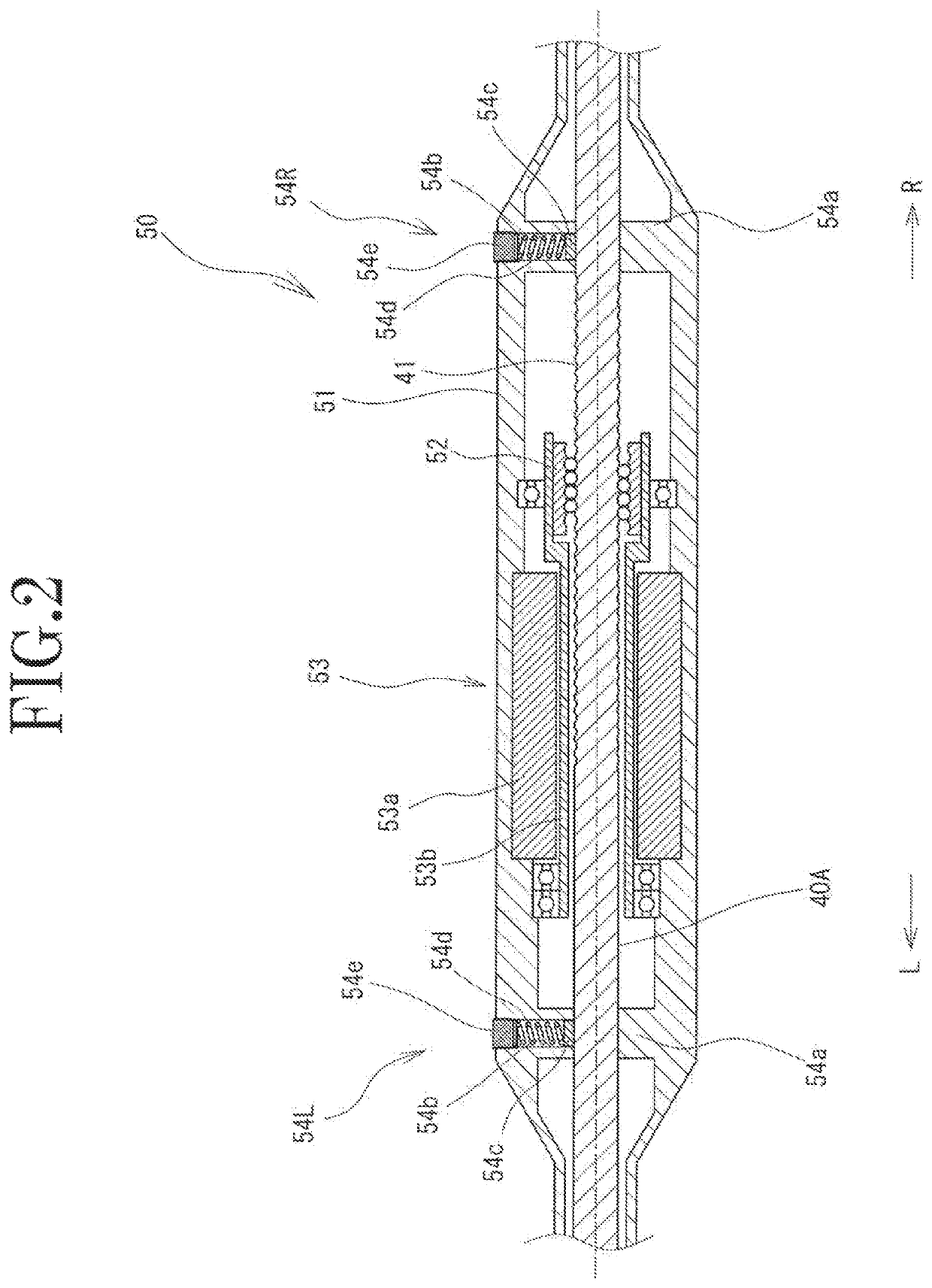
To provide a steering device capable of highly precisely controlling turning angles of steered wheels without changing a layout of members. Provided is a steering device (10A) including: a center arm (26) having one end portion configured to swing in a right-and-left direction with respect to a vehicle body (BD) in synchronism with rotation of a steering shaft (22); a rod member (40A), which is coupled to the one end of the center arm (26), and is configured to move in the right-and-left direction, to thereby change turning angles of steered wheels (WR and WL); and a rod-member drive device (50) configured to linearly move the rod member (40A) in the right-and-left direction through use of a driving force source. The rod member (40A) is supported such that movement of the rod member (40A) in the right-and-left direction of the vehicle body (BD) is allowed, but movement of the rod member (40A) in a front-and-rear direction and an up-and-down direction of the vehicle body (BD) is restricted. The one end portion the center arm (26) and the rod member (40A) are coupled so as to be relatively movable in the front-and-rear direction of the vehicle body (BD).
Description
BACKGROUND OF THE INVENTION1. Field of the Invention[0001]The present invention relates to a steering device of a ball-nut type for a vehicle including a pitman arm.2. Description of the Related Art[0002]Hitherto, there has been used a steering device of a ball nut type for a vehicle of a so-called cab over-engine type. The steering device of the ball-nut type is configured to transmit rotation of a steering wheel to knuckle arms through members such as a ball nut, a pitman arm, a drag link, a center arm, rod members, and tie rods, to thereby change turning angles (steered angles) of steered wheels (see Japanese Patent Application Laid-open No. 553-116634). Meanwhile, as another configuration of the steering device of the ball-nut type, there has been known a configuration in which a drive device (motor actuator) is arranged for each of right and left ball nuts to apply a steering assist force through use of those drive devices (see Japanese Patent Application Laid-open No. 2007-118...
Claims
Application Information
Patent Timeline
Application Date:The date an application was filed.
Publication Date:The date a patent or application was officially published.
First Publication Date:The earliest publication date of a patent with the same application number.
Issue Date:Publication date of the patent grant document.
PCT Entry Date:The Entry date of PCT National Phase.
Estimated Expiry Date:The statutory expiry date of a patent right according to the Patent Law, and it is the longest term of protection that the patent right can achieve without the termination of the patent right due to other reasons(Term extension factor has been taken into account ).
Invalid Date:Actual expiry date is based on effective date or publication date of legal transaction data of invalid patent.

