
Rolling plate assembly attachment for portable power cutting tools including an improved structural design, improved wheel configuration, and a cutting guide

a technology of portable power cutting tools and assembly attachments, which is applied in the direction of manufacturing tools, portable power driven saws, woodworking apparatus, etc., can solve the problems of reducing the possibility of cutting blades being caused, reducing the possibility of cutting rotary saw reducing the possibility of cutting blades being kicked back, so as to facilitate safe rolling movement of portable cutting tools, facilitate strong weight and torsional stress memory, and increase horizontal surface

Active Publication Date: 2019-07-18
CIRCSAW TECH LLC
View PDF6 Cites 1 Cited by
  • Summary
  • Abstract
  • Description
  • Claims
  • Application Information

AI Technical Summary

Benefits of technology

The present invention is an attachable rolling plate assembly that is designed to safely move a portable cutting tool on a workpiece. The assembly is made of a strong and lightweight plastic frame with wheel housings that can hold a cutting tool. The assembly also includes a cutting guide for straight cuts, reduced torsional rotation, and repeated rapid cuts. The attachment member that attaches the cutting tool to the assembly is made of injection molded fiber enriched plastic with an increased flat plate surface area and adjustable power saw retaining members. The attachment member is securely retained on the rolling plate assembly, reducing weight and increasing strength while facilitating ease of operation. The rolling assembly includes one long front and one long rear wheel, each extending for almost the entire width of a housing member, to improve traction and stability on the workpiece.

Problems solved by technology

This improvement thereby reduces the possibility that the cutting blade will be caused to move out of alignment and thereby bind to the workpiece during cutting.
The improvement therefore significantly reduces the possibility of a kick-back of the cutting rotary saw against the worker operating the power tool.

Method used


Image

  • Rolling plate assembly attachment for portable power cutting tools including an improved structural design, improved  wheel configuration, and a cutting guide
  • Rolling plate assembly attachment for portable power cutting tools including an improved structural design, improved  wheel configuration, and a cutting guide
  • Rolling plate assembly attachment for portable power cutting tools including an improved structural design, improved  wheel configuration, and a cutting guide

Examples


Embodiment Construction

[0069]Although specific embodiments of the present invention will now be described with reference to the drawings, it should be understood that such embodiments are by way of example only and merely illustrative of but a small number of the many possible specific embodiments which can represent applications of the principles of the present invention. Various changes and modifications obvious to one skilled in the art to which the present invention pertains are deemed to be within the spirit, scope and contemplation of the present invention as further defined in the appended claims.

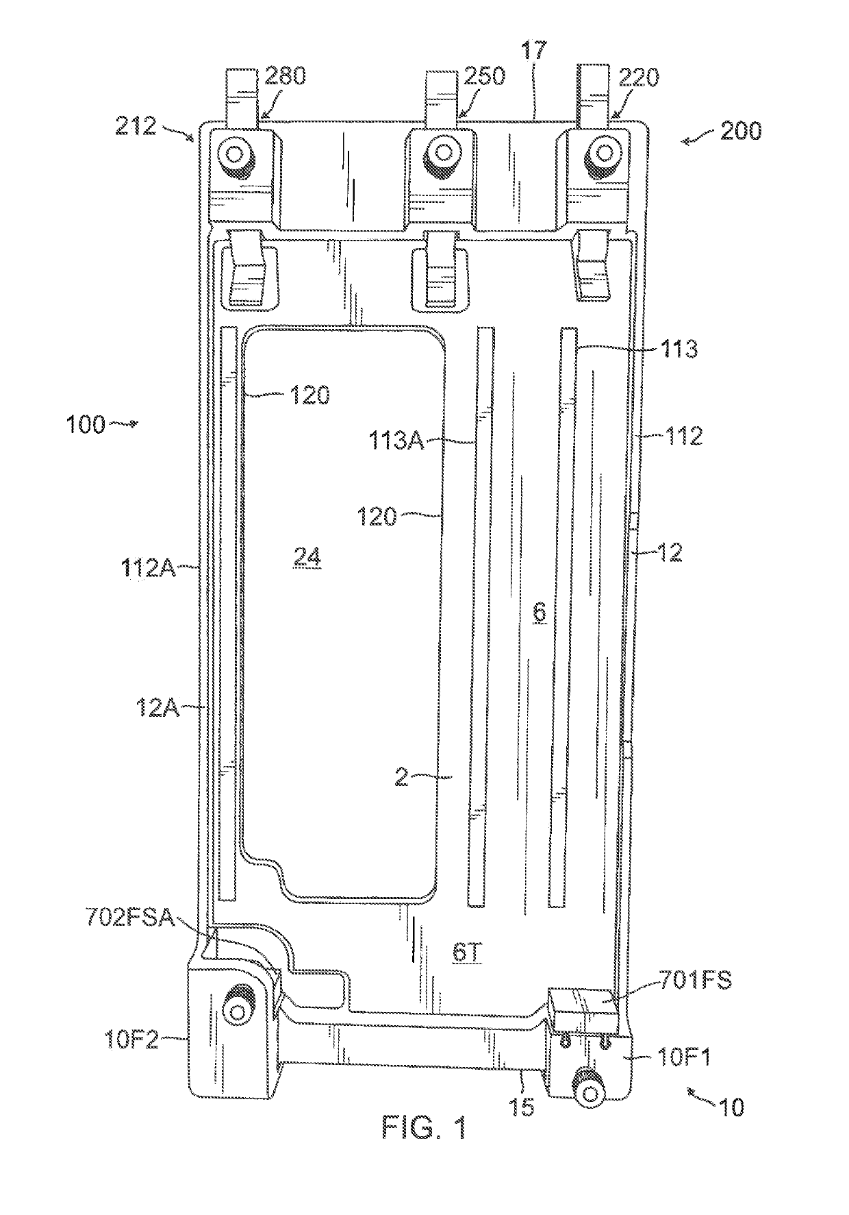
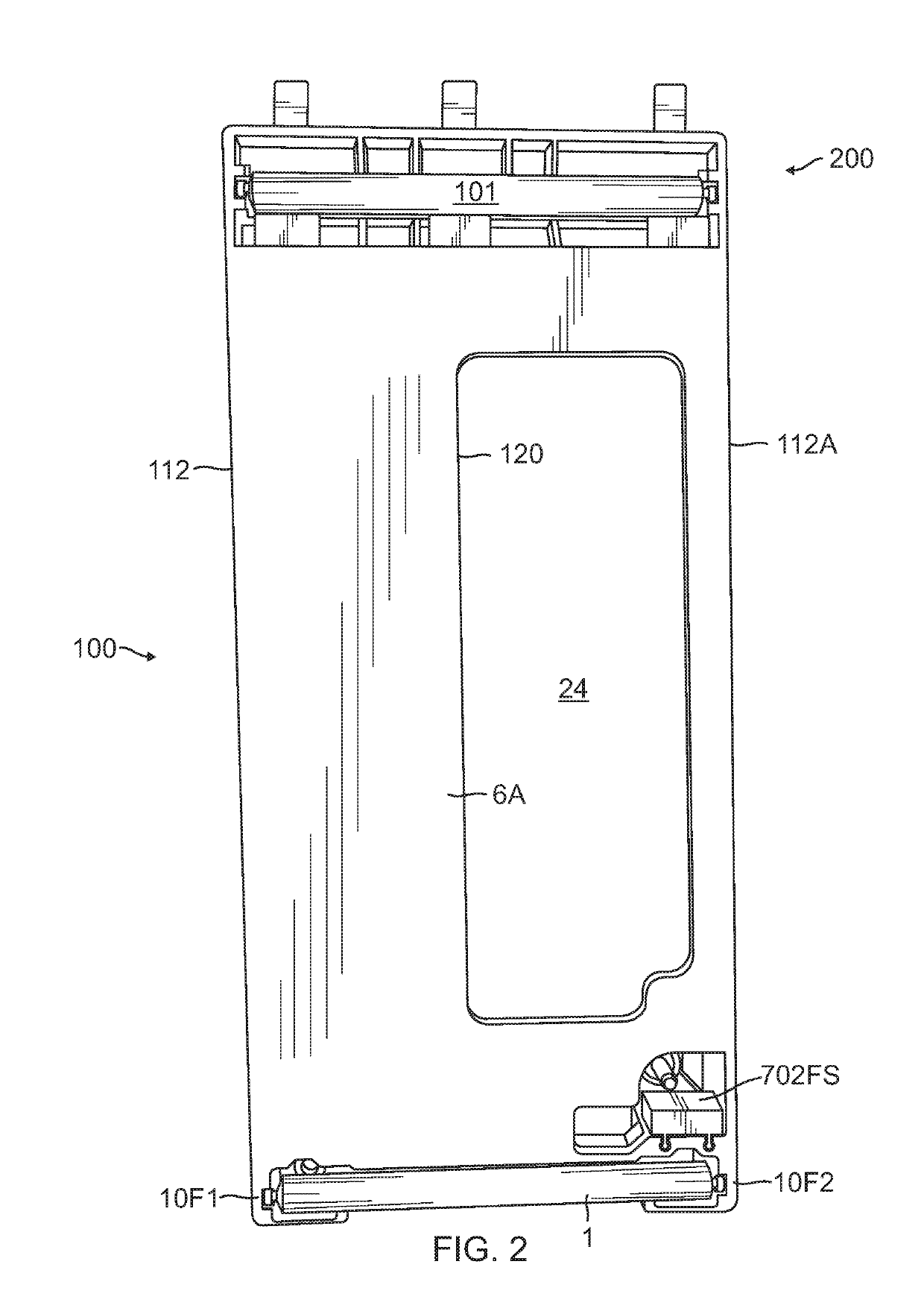
[0070]Referring to FIG. 1, there is illustrated a top plan view of the improved rolling plate assembly 100 without the cutting guide inserted and without a power saw retained. Referring to FIG. 2, there is illustrated a bottom plan view of the improved rolling plate assembly 100 without the cutting guide inserted and without a power saw retained.

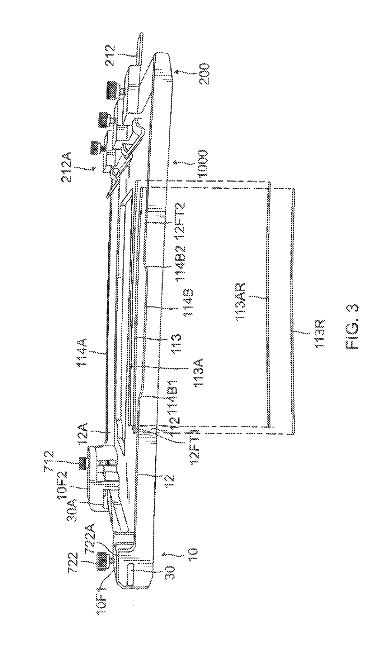
[0071]Referring to FIG. 3, there is illustrated a left side e...


PUM


Abstract

The present invention is an attachable rolling plate assembly which can be attached as a single unit to a portable cutting tool to facilitate the safe rolling movement of the portable cutting tool on the workpiece. The invention comprises a frame assembly formed from a single piece of molded material such as fiber enriched plastic having a pair of oppositely disposed longitudinal sidewalls with stabilizer ribs extending therefrom, and a flat base portion having and opening through which a saw of a power saw extends. The plate has front and rear fastening members to retain a plate of a power cutting saw onto the rolling plate assembly. The invention also includes a cutting guide assembly to facilitate a straight cut, reduce torsional rotation of the saw blade and reduce kickback of the saw.

Description

CROSS-REFERENCE TO RELATED APPLICATION[0001]This patent application claims priority to Provisional Application Ser. No. 62 / 480,824 filed on Apr. 3, 2017, now pending.BACKGROUND OF THE INVENTION[0002]1. Field of the Invention[0003]The present invention relates to the field of portable power cutting tools and to an apparatus which facilitates the ease and safety of handling the portable power cutting tool during the operation of the tool.[0004]2. Description of the Prior Art[0005]Portable power circular saws, jig saws, and other power cutting tools are widely used. Most conventional circular saws come with a flat plate attached to the bottom of the circular saw. When the circular saw is in use to cut a workpiece, the bottom plate of the circular saw comes in contact with the workpiece and slides on the workpiece as the circular saw is moving forward along the cutting direction.[0006]The problem with the conventional flat plate device is that during the cutting operation, extra effort ...

Claims


Application Information

Patent Timeline
IPC IPC(8): B27B9/02B27B9/04
CPCB27B9/02B27B9/04B27B9/00
Inventor KNIGHT, ERIC
Owner CIRCSAW TECH LLC
Learn More