
Rolling plate assembly attachment for portable power cutting tools including an improved structural design and manufactured out of improved materials, an improved wheel configuration, and an adjustable bevel gear and a cutting guide

a portable power cutting tool and rolling plate technology, which is applied in the direction of metal sawing accessories, manufacturing tools, metal sawing devices, etc., can solve the problems of reducing the accuracy of cutting, requiring extra effort from the user of the circular saw, and dangerous situations such as kickback, so as to facilitate safe rolling movement of the portable cutting tool, facilitate strong weight and torsional stress memory, and improve the structural design

Active Publication Date: 2012-05-22
CIRCSAW TECH LLC
View PDF85 Cites 12 Cited by
  • Summary
  • Abstract
  • Description
  • Claims
  • Application Information

AI Technical Summary

Benefits of technology

"The present invention is an attachable rolling plate assembly for a portable cutting tool that can be easily attached to a rotary power cutting tool and safely rolled on the workpiece during operation. The assembly includes a frame assembly made of injection molded fiber enriched plastic with stabilizer fins and a front and back wheel housing portions. The assembly also includes removable wheels for easy replacement, as well as a cutting guide for straight line cutting. The rolling plate assembly helps to reduce weight and torsional stress on the tool, while also improving traction and stability during the cutting process. The wheels on the rolling plate assembly can also absorb vibration from the power tool and provide improved ease of rolling. The attachment means for the power tool can be quickly attached and saved time and effort during the cutting process. The rolling plate assembly is also designed to facilitate a quick attachment to the cutting tool."

Problems solved by technology

The problem with the conventional flat plate device is that during the cutting operation, extra effort is required from the user of the circular saw to overcome the friction between the bottom plate attached to the circular saw and the work-piece.
In addition, the standard attachment plates are heavy and have a tendency to slide in a side-to-side motion which often reduces the accuracy of the cut.
In addition, rotatory power cutting tools such as a rotary power saw can create a dangerous situation called kick-back.
The heavy weight of the saw causes the saw blade to move out of the linear motion due to an unstable frictional binding of the flat attachment plate against the workpiece.
As a result of this veering of the blade off a straight line motion, the blade may bind with the workpiece and subsequently kick back against the worker, thereby possibly causing serious injury to the worker.
First, the wheel attachment devices must be individually placed on the saw bracket which is time consuming and results in extra effort.
In addition, the wheels are not replaceable and if one wheel is broken or is worn, it may affect the operation of the rotary power saw.

Method used


Image

  • Rolling plate assembly attachment for portable power cutting tools including an improved structural design and manufactured out of improved materials, an improved wheel configuration, and an adjustable bevel gear and a cutting guide
  • Rolling plate assembly attachment for portable power cutting tools including an improved structural design and manufactured out of improved materials, an improved wheel configuration, and an adjustable bevel gear and a cutting guide
  • Rolling plate assembly attachment for portable power cutting tools including an improved structural design and manufactured out of improved materials, an improved wheel configuration, and an adjustable bevel gear and a cutting guide

Examples


Embodiment Construction

[0130]Although specific embodiments of the present invention will now be described with reference to the drawings, it should be understood that such embodiments are by way of example only and merely illustrative of but a small number of the many possible specific embodiments which can represent applications of the principles of the present invention. Various changes and modifications obvious to one skilled in the art to which the present invention pertains are deemed to be within the spirit, scope and contemplation of the present invention as further defined in the appended claims.

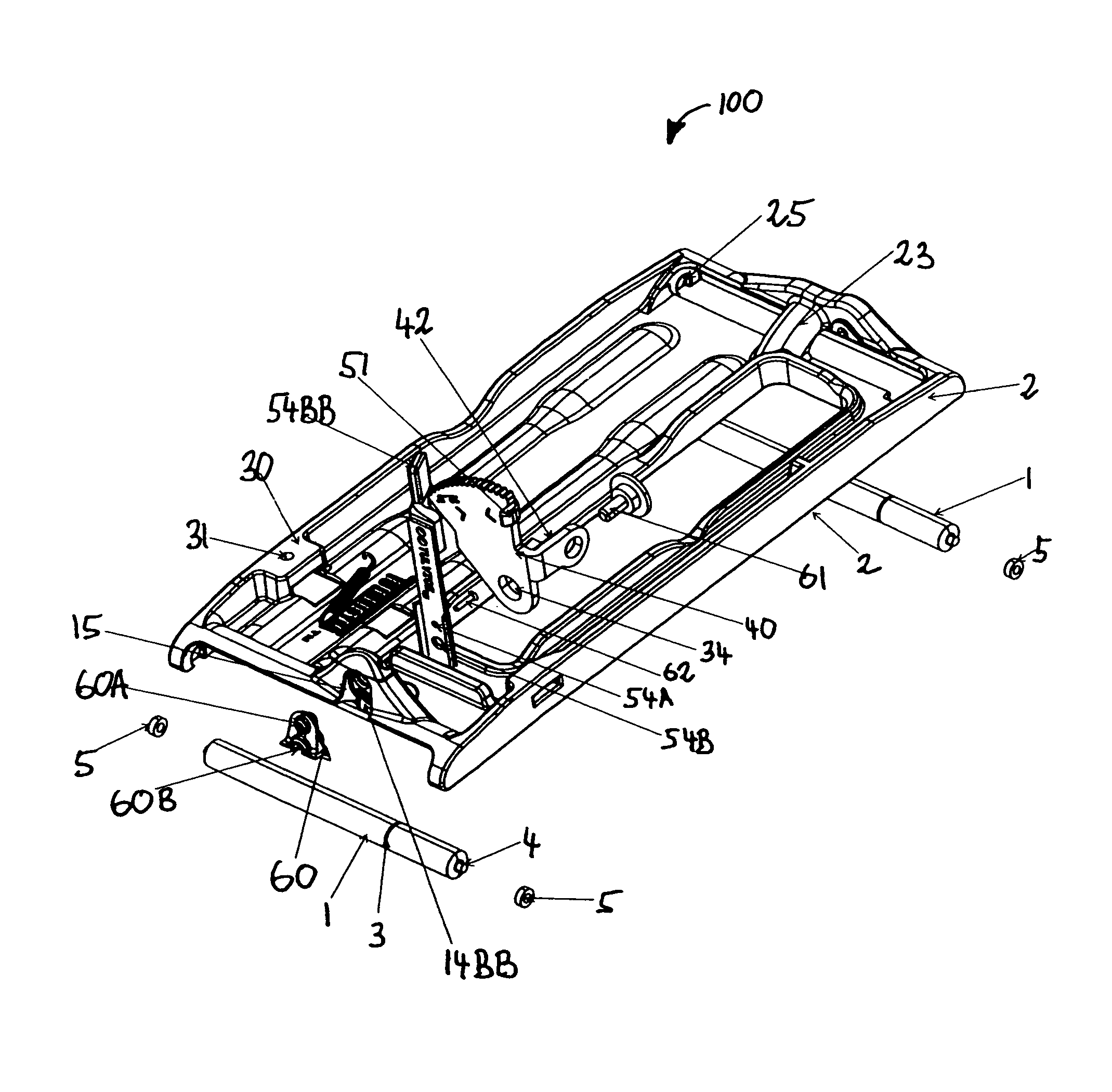
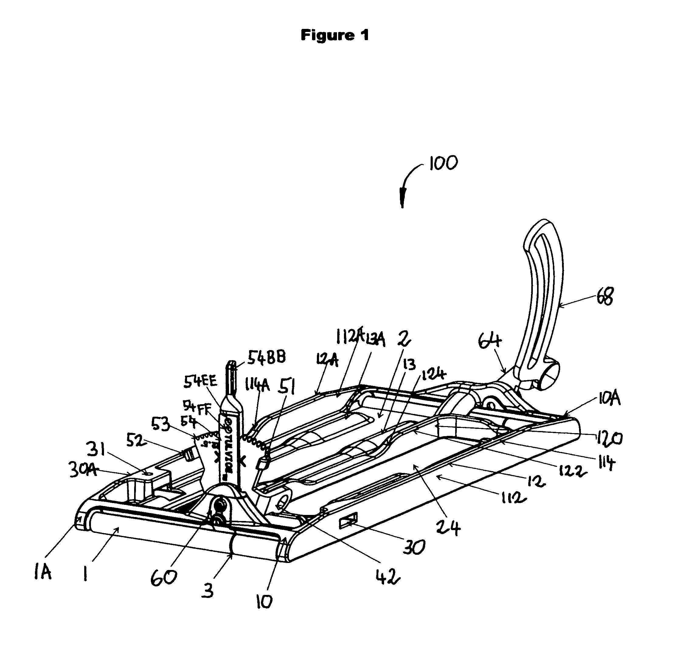
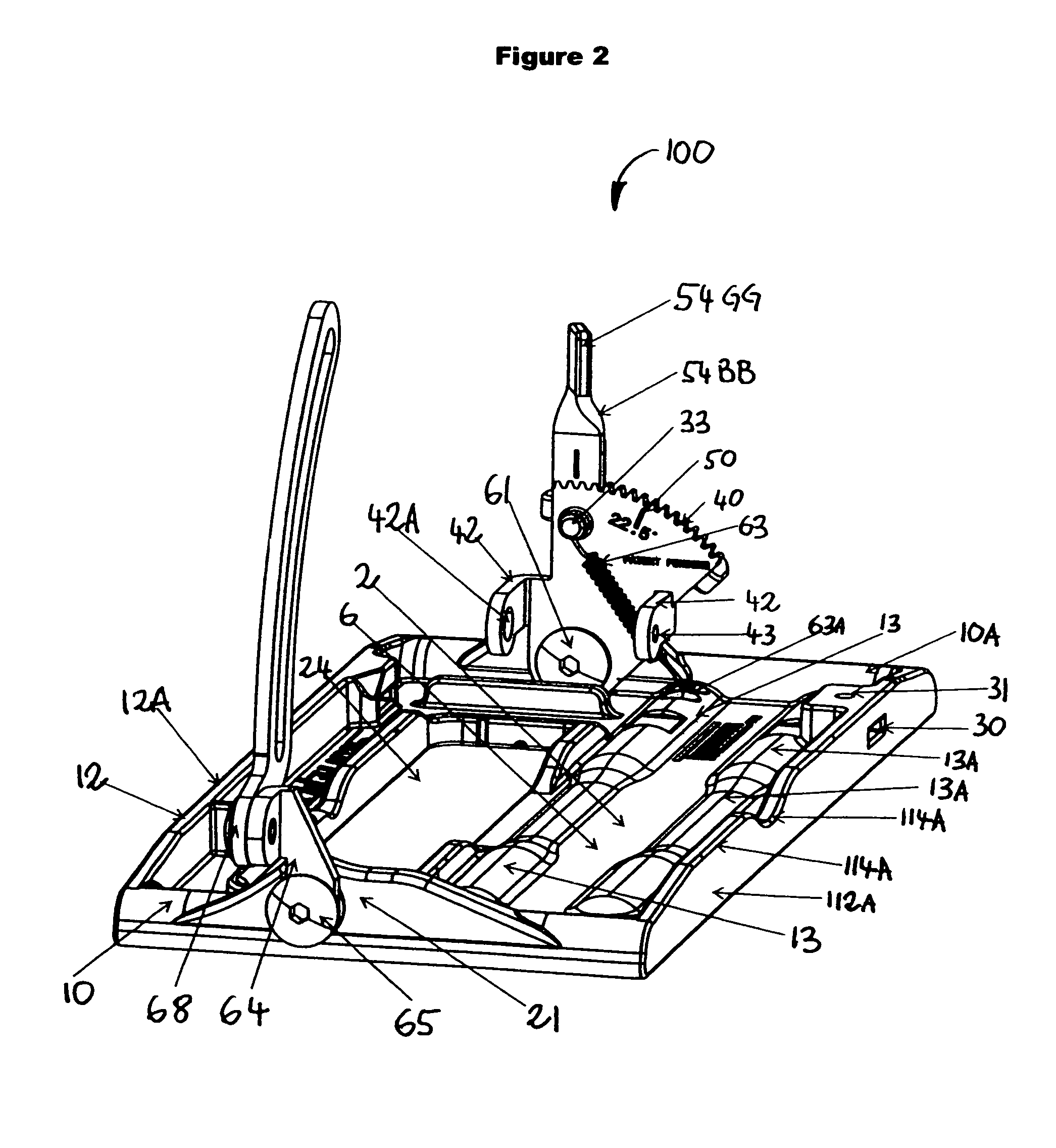
[0131]Referring to FIG. 1, there is illustrated a front perspective view of the fully assembled improved rolling plate assembly 100. In FIG. 2 there is illustrated a rear perspective view of the fully assembled improved rolling plat assembly 100. In FIG. 3 there is illustrated a an exploded front perspective view of the rolling plate assembly 100. In FIG. 4 there is illustrated an exploded rear perspective...


PUM

PropertyMeasurementUnit
angleaaaaaaaaaa
angleaaaaaaaaaa
angleaaaaaaaaaa

Abstract

The present invention is an attachable rolling plate assembly which can be attached as a single unit to a portable cutting tool to facilitate the safe rolling movement of the portable cutting tool on the workpiece. The invention comprises a frame assembly formed from a single piece of molded material such as fiber enriched plastic having a pair of oppositely disposed longitudinal sidewalls with stabilizer fins extending therefrom, and a flat base portion having a pair of parallel stabilizer tubes molded therein. The invention further includes an adjustable bevel gear assembly by which the angle of orientation of the cutting blade can be quickly changed. The invention also includes a cutting guide assembly to facilitate a straight cut, reduce torsional rotation of the saw blade and reduce kickback of the saw.

Description

[0001]This is a divisional patent application of patent application Ser. No. 11 / 801,405 filed on May 9, 2007 now U.S. Pat. No. 7,958,641.BACKGROUND OF THE INVENTION[0002]1. Field of the Invention[0003]The present invention relates to the field of portable power cutting tools and to an apparatus which facilitates the ease and safety of handling the portable power cutting tool during the operation of the tool.[0004]2. Description of the Prior Art[0005]Portable power circular saws, jig saws, and other power cutting tools are widely used. Most conventional circular saws come with a flat plate attached to the bottom of the circular saw. When the circular saw is in use to cut a workpiece, the bottom plate of the circular saw comes in contact with the workpiece and slides on the workpiece as the circular saw is moving forward along the cutting direction.[0006]The problem with the conventional flat plate device is that during the cutting operation, extra effort is required from the user of ...

Claims


Application Information

Patent Timeline
Patent Type & Authority Patents(United States)
IPC IPC(8): B23D47/02
CPCB27B9/02Y10T83/5851Y10T83/8878Y10T83/667
Inventor ENDE, MATHIAS AM
Owner CIRCSAW TECH LLC
Learn More