Rolling plate assembly attachment for portable power cutting tools

a technology of portable power cutting tools and rolling plates, which is applied in the direction of metal sawing accessories, band saws, manufacturing tools, etc., can solve the problems of reducing the accuracy of cutting, requiring extra effort from the user of the circular saw, and dangerous situations such as kickbacks, so as to facilitate the safe rolling movement of the portable cutting tool

Active Publication Date: 2010-02-16
CIRCSAW TECH LLC
View PDF12 Cites 21 Cited by
  • Summary
  • Abstract
  • Description
  • Claims
  • Application Information

AI Technical Summary

Benefits of technology

[0009]The present invention is an attachable rolling plate assembly which can be attached as a single unit to a portable cutting tool to facilitate the safe rolling movement of the portable cutting tool on the workpiece. The invention comprises a front wheel housing portion, a back wheel housing portion, and three metal rods which interconnect the two housings. The housings removably retain a pair of spaced apart wheels and means to retain a cutting tool on the housings so that the cutting tool can be rolled on the workpiece during operation of the tool while the cutting blade portion of the tool extends between a pair of adjacent interconnecting rod members.

Problems solved by technology

The problem with the conventional flat plate device is that during the cutting operation, extra effort is required from the user of the circular saw to overcome the friction between the bottom plate attached to the circular saw and the work-piece.
In addition, the standard attachment plates are heavy and have a tendency to slide in a side-to-side motion which often reduces the accuracy of the cut.
In addition, rotatory power cutting tools such as a rotary power saw can create a dangerous situation called kick-back.
The heavy weight of the saw causes the saw blade to move out of the linear motion due to an unstable frictional binding of the flat attachment plate against the workpiece.
As a result of this veering of the blade off a straight line motion, the blade may bind with the workpiece and subsequently kick back against the worker, thereby possibly causing serious injury to the worker.
First, the wheel attachment devices must be individually placed on the saw bracket which is time consuming and results in extra effort.
In addition, the wheels are not replaceable and if one wheel is broken or is worn, it may affect the operation of the rotary power saw.

Method used


Image

  • Rolling plate assembly attachment for portable power cutting tools
  • Rolling plate assembly attachment for portable power cutting tools
  • Rolling plate assembly attachment for portable power cutting tools

Examples


Embodiment Construction

[0038]Although specific embodiments of the present invention will now be described with reference to the drawings, it should be understood that such embodiments are by way of example only and merely illustrative of but a small number of the many possible specific embodiments which can represent applications of the principles of the present invention. Various changes and modifications obvious to one skilled in the art to which the present invention pertains are deemed to be within the spirit, scope and contemplation of the present invention as further defined in the appended claims.

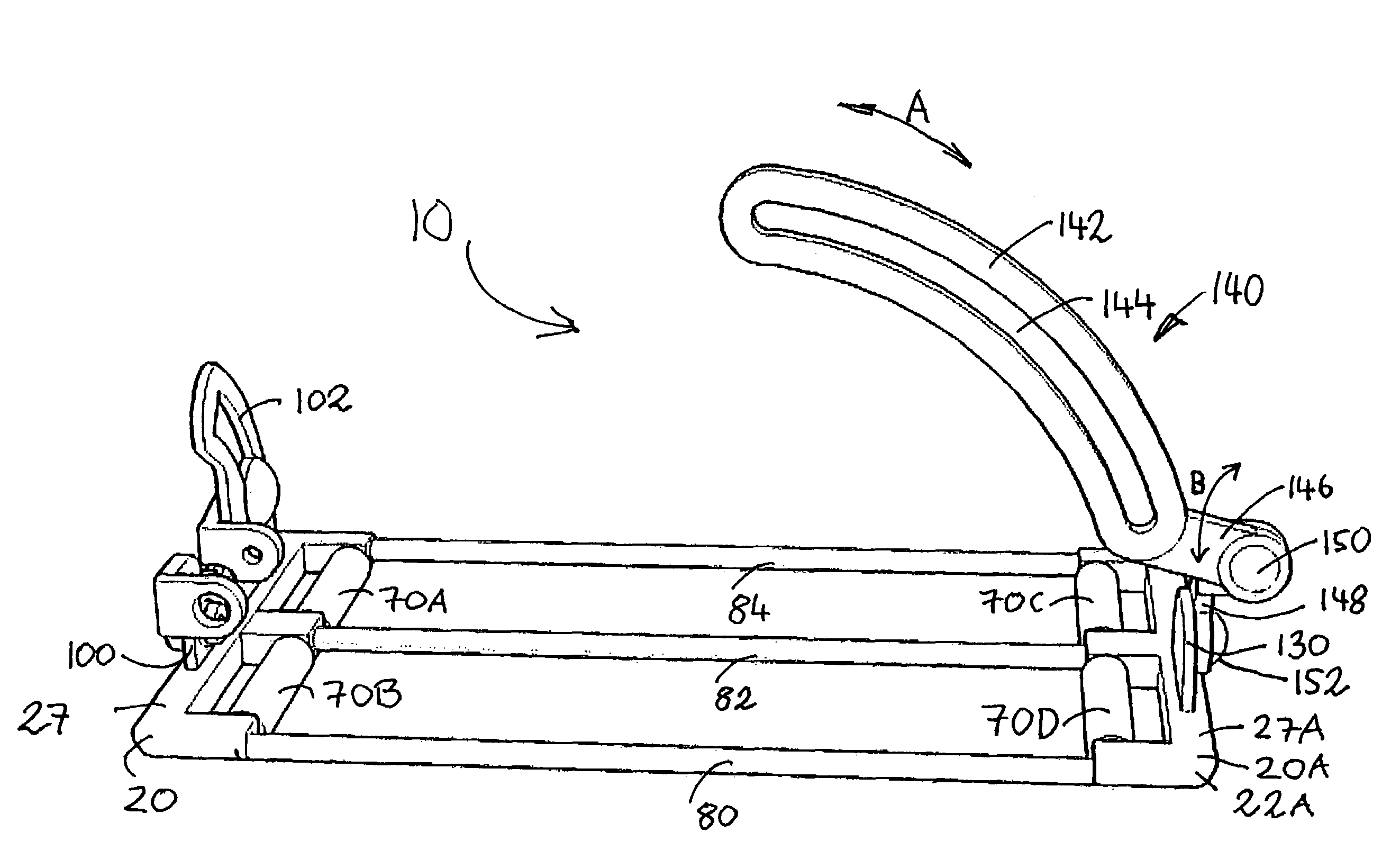
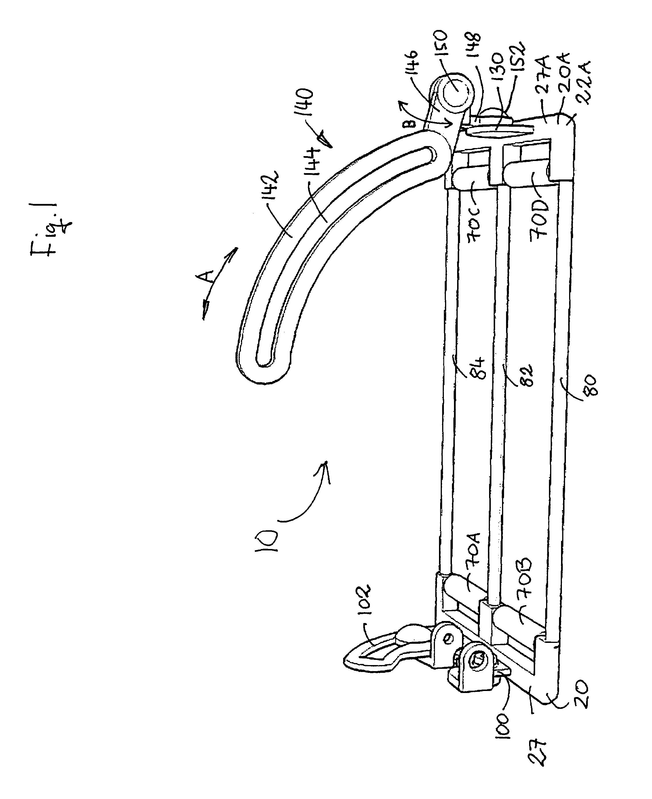
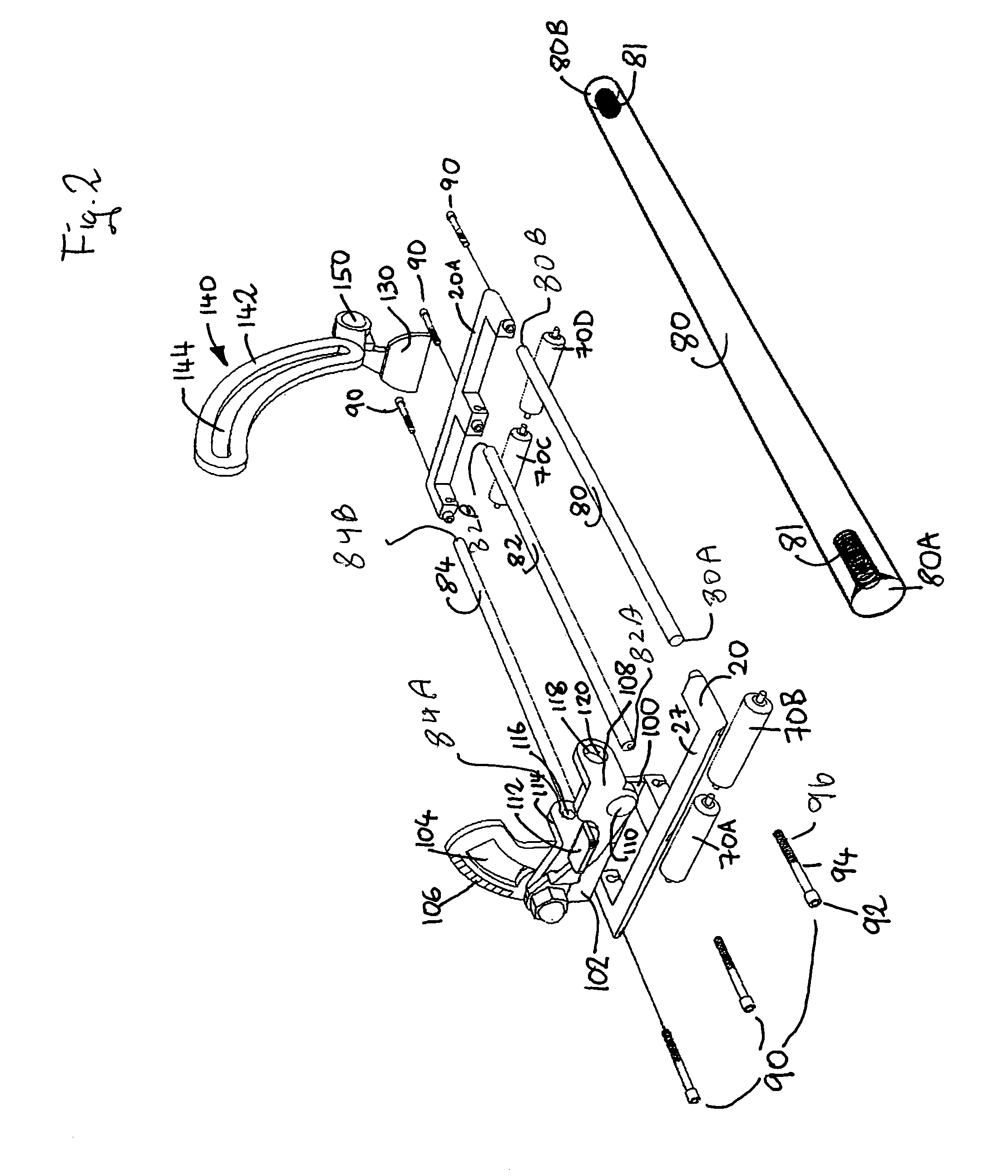
[0039]Referring to FIG. 1, there is illustrated a perspective view of the fully assembled rolling plate assembly 10 and FIG. 2 is an exploded view to better illustrate the component parts and how they are assembled together. The rolling plate assembly 10 assembly comprises a first housing member 20 and a second housing member 20A which is a mirror image of the first housing member 20. As will be discussed ...


PUM

PropertyMeasurementUnit
diameter D1aaaaaaaaaa
diameteraaaaaaaaaa
frictionaaaaaaaaaa

Abstract

The present invention is an attachable rolling plate assembly which can be attached as a single unit to a portable cutting tool to facilitate the safe rolling movement of the portable cutting tool on the workpiece. The invention comprises a front wheel housing portion, a back wheel housing portion, and two or three metal rods which interconnect the two housings. The housings removably retain a pair of spaced apart wheels and means to retain a cutting tool on the housings so that the cutting tool can be rolled on the workpiece during operation of the tool while the cutting blade portion of the tool extends between a pair of adjacent interconnecting rod members. The front and rear wheel housing assembly receives the cutting blade in between its pins or axles, so that the entire width of the saw plate is supported by the wheels during cutting.

Description

BACKGROUND OF THE INVENTION [0001]1. Field of the Invention[0002]The present invention relates to the field of portable power cutting tools and to an apparatus which facilitates the ease and safety of handling the portable power cutting tool during the operation of the tool.[0003]2. Description of the Prior Art[0004]Portable power circular saws are widely used. Most conventional circular saws come with a flat plate attached to the bottom of the circular saw. When the circular saw is in use to cut a workpiece, the bottom plate of the circular saw comes in contact with the workpiece and slides on the workpiece as the circular saw is moving forward along the cutting direction.[0005]The problem with the conventional flat plate device is that during the cutting operation, extra effort is required from the user of the circular saw to overcome the friction between the bottom plate attached to the circular saw and the work-piece. In addition, the standard attachment plates are heavy and hav...

Claims


Application Information

Patent Timeline
Patent Type & Authority Patents(United States)
IPC IPC(8): B27B9/02B23D59/00B27B9/04B26D3/02B26D5/08B26D7/01
CPCB27B9/02Y10T83/6945Y10T83/7264Y10T83/8773Y10T83/869Y10T83/695
Inventor ENDE, MATHIAS AM
Owner CIRCSAW TECH LLC
Why Eureka
Try Eureka