Linear device

a technology of a linear device and a lubricant layer, which is applied in the direction of linear bearings, bearing components, bearings, etc., can solve the problems of inability to prevent a gap formation between and the danger of lubricant escaping from the end plate unit and the main body

Inactive Publication Date: 2006-02-02
REXROTH STAR
View PDF9 Cites 14 Cited by
  • Summary
  • Abstract
  • Description
  • Claims
  • Application Information

AI Technical Summary

Benefits of technology

[0008] Accordingly, it is an object of the present invention to provide a linear device, which avoids the disadvantages of the prior art.

Problems solved by technology

EP 1 416 178 A2 is based on a prior art in which the end plate unit was attached to the main body by means of only two fastening elements, which made it impossible to prevent a gap formation between the end plate unit and the main body and the attendant danger of an undesired escape of lubricant between the end plate unit and main body.

Method used


Image

  • Linear device
  • Linear device
  • Linear device

Examples


Embodiment Construction

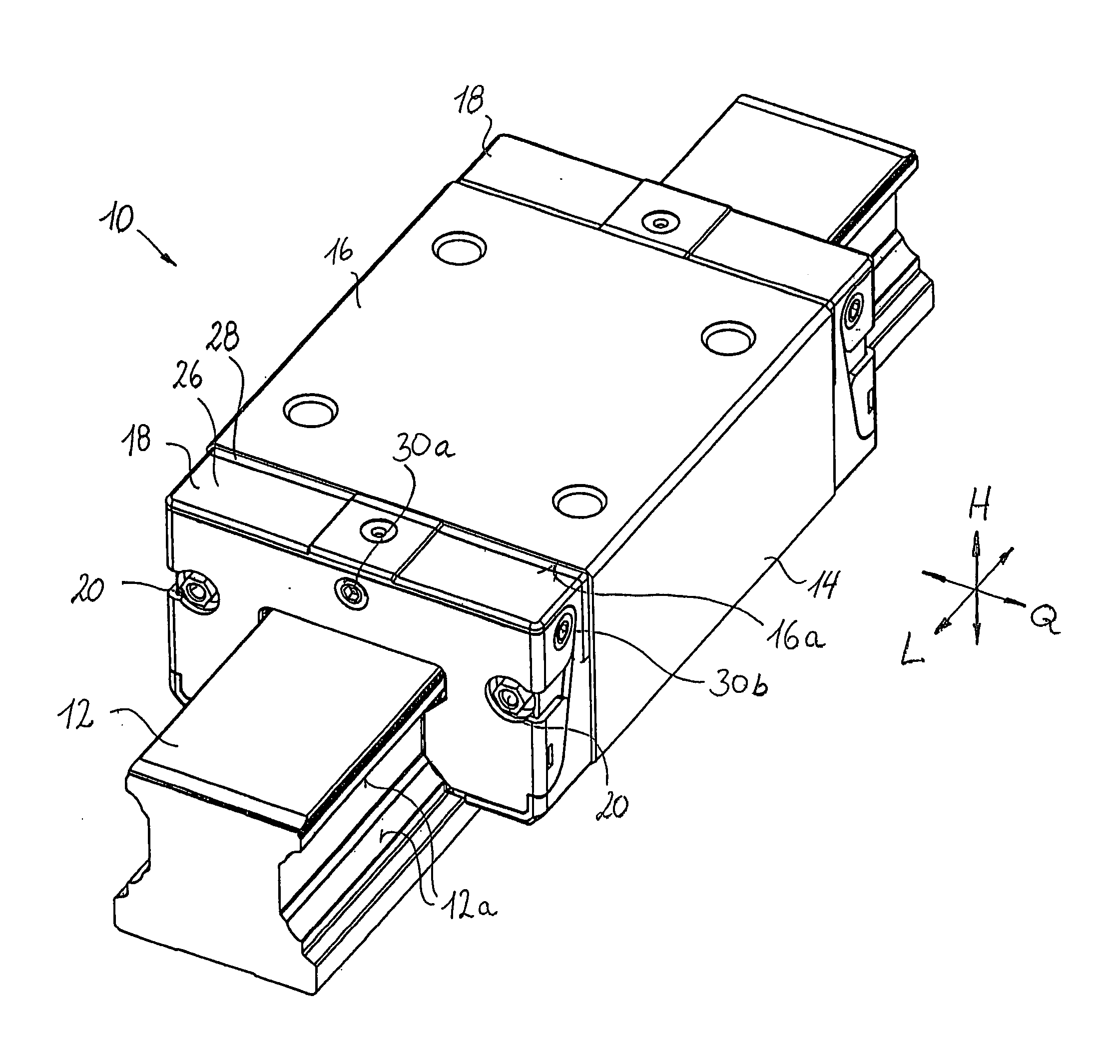
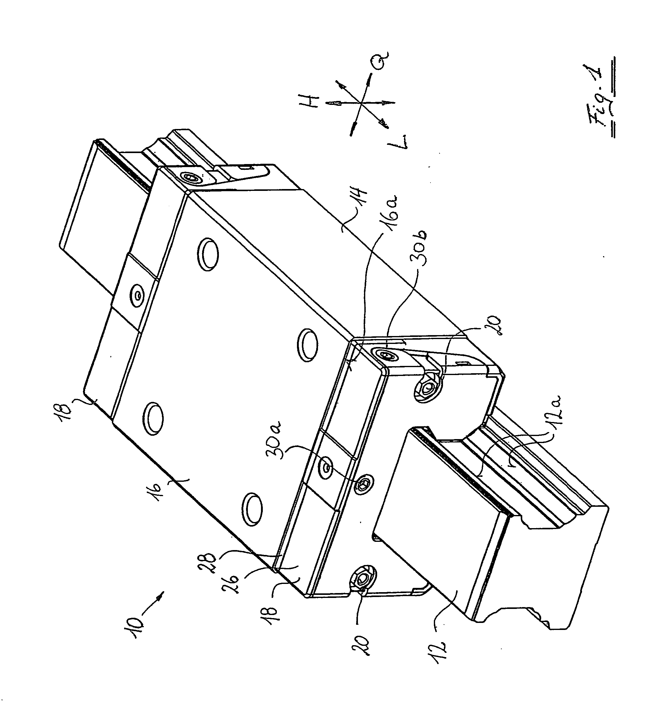
[0024] In FIG. 1, a linear guide device according to the present invention is labeled as a whole with the reference numeral 10. It includes an elongated guide rail 12 extending in the longitudinal direction L and a guide carriage 14 that is guided on the guide rail 12 and can move in relation to it along its longitudinal axis L.

[0025] The guide carriage 14 has a main body 16 and two essentially identically embodied end plate units 18. Each of the two end plate units 18 is attached to the main body 16 of the guide carriage 14 by means of only two fastening screws 20.

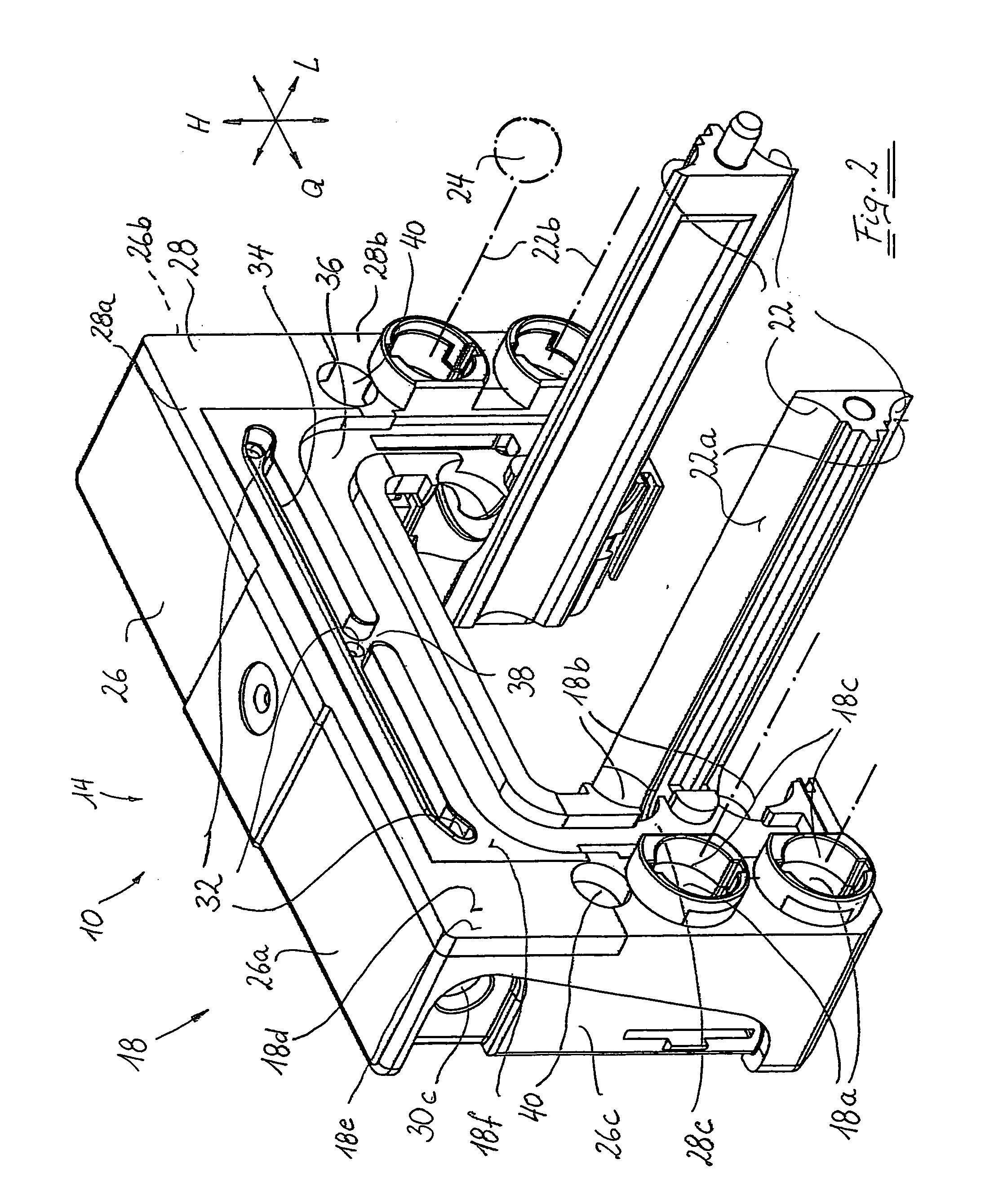
[0026] In the exemplary embodiment depicted, the guide carriage 14 contains four endless rolling element tracks 22 (see FIG. 2), each of which includes a load-bearing rolling element channel segment, a return channel segment, and two deflecting channel segments that connect the load-bearing rolling element channel segment and the return channel segment to each other. The load-bearing rolling element channel segment here...


PUM


Abstract

A linear device has an essentially rod-shaped functional unit and a functional unit that at least partially encompasses the rod-shaped functional unit and includes a main body and at least one end plate unit that rests with a contact surface against the main body in which a lubrication groove is provided, which is open toward the contact surface and extends at least partially in the circumference direction around the rod-shaped functional unit, and it is possible to fasten the end plate unit to the main body by only two fastening elements, and a region of the contact surface adjacent to the lubrication groove and encompassing this lubrication groove is raised in relation to the rest of the contact surface.

Description

BACKGROUND OF THE INVENTION [0001] The present invention relates to a linear device. [0002] More particularly, it relates to a linear device which has a first, essentially rod-shaped functional unit and a second functional unit that at least partially encompasses the rod-shaped functional unit; and are able to move in relation to each other by means of at least one endless rolling element track, which includes a load-bearing rolling element channel segment, a return channel segment, and two deflecting channel segments that connect the load-bearing rolling element channel segment and the return channel segment to each other; the second functional unit has a main body and at least one end plate unit, which rests with a contact surface against an end surface of the main body and contains a deflecting channel segment of the rolling element track; and a lubrication groove, which is open toward the contact surface and extends at least partially in the circumference direction around the ro...

Claims


Application Information

Patent Timeline
Patent Type & Authority Applications(United States)
IPC IPC(8): F16C29/06F16C33/10
CPCF16C29/0609F16C33/6622F16C29/0645
Inventor HAUB, ALFRED
Owner REXROTH STAR
Why Eureka
Try Eureka