
Oil flow switch and lubrication system with the same for a refrigeration system

a technology of lubrication system and flow switch, which is applied in the direction of lubrication check valves, light and heating apparatus, refrigeration components, etc., can solve the problems of reducing the density of oil solution, neither of the switches can accurately sense whether the liquid level is proper, and the float level switch cannot accurately detect the liquid level. , to achieve the effect of effectively preventing false alarms caused by various reasons

Active Publication Date: 2022-04-05
JOHNSON CONTROLS AIR CONDITIONING & REFRIGERATION WUXI +2
View PDF10 Cites 0 Cited by
  • Summary
  • Abstract
  • Description
  • Claims
  • Application Information

AI Technical Summary

Benefits of technology

The present invention relates to an oil flow switch that can be placed in a compressor's oil circulating passage. When oil flows through the switch, a bell-shaped chamber fills with oil, causing the switch to turn on. When there is no oil flow, the oil returns to the main oil pipe, causing the switch to turn off. This prevents false alarms caused by any reason and ensures the oil flow switch stays on as long as oil flows in the passage.

Problems solved by technology

During use, it is found that both of the float level switch and the photoelectric level switch have a drawback: once bubbles exist in the liquid, neither of the switches can accurately sense whether the liquid level is proper.
This will cause a decrease in the density of the oil solution and a failure of the float of the float level switch to float, and consequently the level switch will emit a false level signal.
Likewise, for the photoelectric liquid level switch, due to the effervescent oil solution, the light emitted from the photoelectric liquid level switch cannot be successfully refracted back from the prism to the photoelectric switch, which will also cause a false alarm.

Method used


Image

  • Oil flow switch and lubrication system with the same for a refrigeration system
  • Oil flow switch and lubrication system with the same for a refrigeration system
  • Oil flow switch and lubrication system with the same for a refrigeration system

Examples


Embodiment Construction

[0022]Hereinafter, the preferred embodiments of the present disclosure will be described with reference to the accompanying drawings. It needs to be noted that the terms “upper,”“lower,”“front,”“rear,”“left,”“right,” and similar expressions used herein are only for illustration purposes, not intended for limiting.

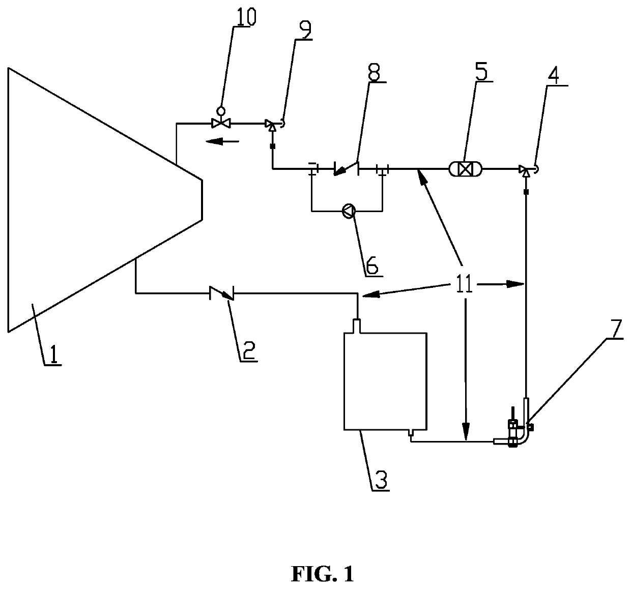
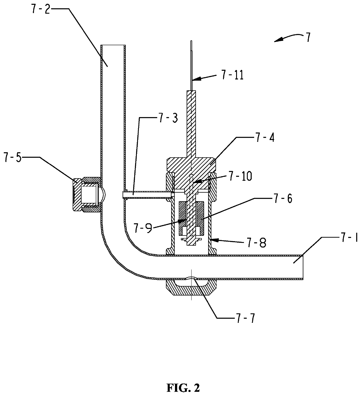
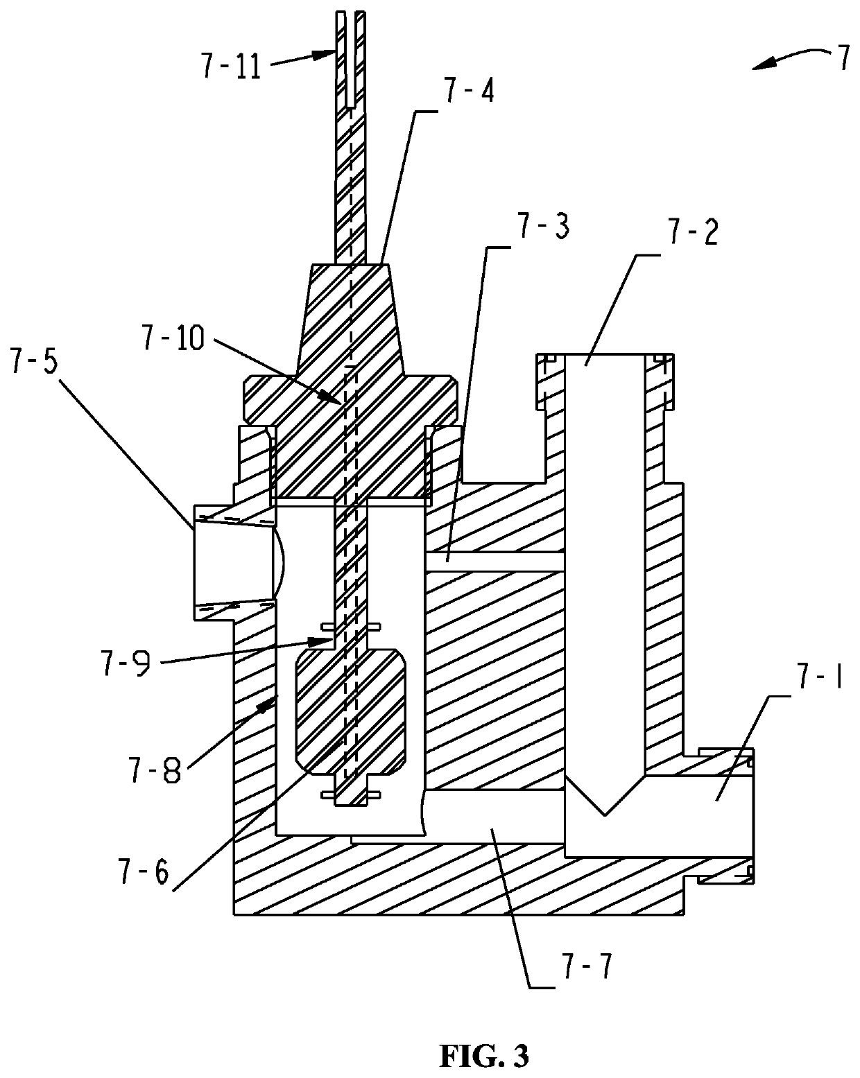
[0023]FIGS. 1-2 illustrate a refrigeration system according to the present disclosure, wherein the refrigeration system may comprise a compressor 1 configured to compress a refrigerant for refrigeration circulation, wherein lubricant in the compressor 1, after being separated in an oil separator of the compressor 1, is guided to an oil storage tank 3 via a first portion of the pipeline 11 and a one-way valve 2, and then is in communication with an oil inlet 7-1 of the float device 7 (also referred to herein as an “oil flow switch”) via a second portion of the pipeline 11. Further, the lubricant flows out of an oil outlet 7-2 of the float device 7 into an angle valve 4, and ...


PUM


Abstract

The present disclosure relates to an oil flow switch, comprising a float device connected to a circulating oil passage and a floating liquid level switch element provided in the float device, wherein the float device comprises an oil inlet, an oil outlet, and a float chamber provided between the oil inlet and the oil outlet, the floating liquid level switch element is provided in the float chamber, and the float device is provided with a channel in communication with the float chamber. The oil flow switch according to the present disclosure may avoid a false alarm of the oil level switch and meanwhile mitigate disturbance to the float caused by liquid level fluctuation to reduce friction between the float and the sleeve rod. Further, a lubrication system with the above oil.

Description

FIELD OF THE INVENTION[0001]The present disclosure generally relates to an oil lubrication technology, and more particularly to an oil flow switch and a lubrication system with the same for a refrigeration system.BACKGROUND OF THE INVENTION[0002]In a refrigeration system, refrigerant oil functions to lubricate, seal, and reduce noise, etc.; therefore, early warning about an oil level of lubricant is critical to ensure system reliability. A float level switch or a photoelectric level switch is commonly employed in current approaches for determining whether the oil level is lower than a predetermined oil level. Specifically, the float level switch is a mechanical liquid level switch in which a float will float under the buoyancy force in the liquid, and will sink once the liquid level is insufficient during which the magnetic field of a magnet built in the float will change, which consequently changes a state of a contact in a reed switch, i.e., changing from a previous off state to a...

Claims


Application Information

Patent Timeline
Patent Type & Authority Patents(United States)
IPC IPC(8): F25B31/00F16N29/00F16N23/00F16N7/40F25B43/00
CPCF16N23/00F16N7/40F16N29/00F25B31/002F25B31/004F25B43/003F16N2210/10F16N2250/18F16N2280/00F25B2500/16F25B2700/03
Inventor LI, JINGXIAO, TIANLONGLI, JINLIANG
Owner JOHNSON CONTROLS AIR CONDITIONING & REFRIGERATION WUXI
Learn More