
Continuous-curvature convex roll for continuously casting bloom, and manufacturing method therefor

a convex roll and continuous curve technology, applied in the field of metal casting, can solve the problems of reducing the rolling pressure or the withdrawal resistance, shortening the sections ab and ef at both ends of the protuberance, and still inevitably stressing the casting slab

Active Publication Date: 2022-04-12
BAOSHAN IRON & STEEL CO LTD
View PDF7 Cites 0 Cited by
  • Summary
  • Abstract
  • Description
  • Claims
  • Application Information

AI Technical Summary

Benefits of technology

The continuous curvature convex roll uniformly deforms casting blooms, reduces cracking, and decreases rolling pressure and withdrawal resistance, while improving the center density and internal quality of the cast material.

Problems solved by technology

The casting slab is still inevitably stressed during the rolling deformation process.
Because the surface temperature of the continuous casting slab is usually 700-900° C., and the surface temperature is not uniform, the singular points become stress concentration points, where cracks tend to be generated in the surface during the rolling deformation process of the casting slab.
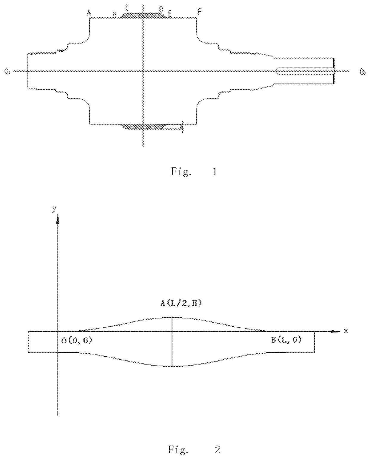
An excessively long transition curve means that the straight line sections AB and EF at both ends of the protuberance become shorter, which is not conducive to reducing the rolling pressure or the withdrawal resistance.

Method used


Image

  • Continuous-curvature convex roll for continuously casting bloom, and manufacturing method therefor

Examples


example 1

[0065]In the coordinate system shown by FIG. 2 (the origin of coordinates was positioned at the middle point O, the two points O and B met second-order derivative continuity, and point A met first-order derivative continuity), the length of the working roll body of the roll was 500 mm; the length of the two straight line sections was AB=EF=135 mm; the length of the intermediate straight line section CD was 150 mm; the projection length of the transition curves BC and DE on the x axis was 40 mm; the height of the protuberance was H=20 mm; and the curve equation of the transition curve BC was:

y=−4.882813×10−9x6+1.171875×10−6x5−9.375×10−5x4+2.5×10−3x3

[0066]The second transition curve DE was formed as a mirror image of the first transition curve BC about a center line passing through the midpoint of the intermediate straight line section CD.

example 2

[0067]In the coordinate system shown by FIG. 2, the length of the working roll body of the roll was 500 mm; the length of the two straight line sections was AB=EF=115 mm; the length of the intermediate straight line section CD was 150 mm; the projection length of the transition curves BC and DE on the x axis was 60 mm; the height of the protuberance was H=20 mm; and the curve equation of the transition curve BC was:

y=−4.286694×10−10x6+1.543210×10−7x5−1.851852×10−5x4+7.407407×10−4x3

[0068]Similarly, the transition curve DE was formed as a mirror image of the transition curve BC about a center line passing through the midpoint of the line section CD.

[0069]The rest was the same as Example 1.

example 3

[0070]In the coordinate system shown by FIG. 2, the length of the working roll body of the roll was 500 mm; the length of the two straight line sections was AB=EF=115 mm; the length of the intermediate straight line section CD was 150 mm; the projection length of the transition curves BC and DE on the x axis was 60 mm; the height of the protuberance was H=30 mm; and the curve equation of the transition curve BC was:

y=−6.430041×10−10x6+2.314815×10−7x5−2.777778×10−5x4+1.111111×10−3x3

[0071]Similarly, the transition curve DE was formed as a mirror image of the transition curve BC about a center line passing through the midpoint of the line section CD.

[0072]The rest was the same as Example 1.


PUM

PropertyMeasurementUnit
surface temperatureaaaaaaaaaa
lengthaaaaaaaaaa
lengthaaaaaaaaaa

Abstract

Disclosed are a continuous-curvature convex roll for continuously casting a bloom, and a manufacturing method therefore. An outer contour curve of a working portion of a body of the continuous-curvature convex roll contains a first straight-line segment (AB), a first transition curve segment (BC), an intermediate straight-line segment (CD), a second transition curve segment (DE) and a second straight-line segment (EF). The BC, the AB, and the CD have continuous first-order derivatives, continuous second-order derivatives, and continuous curvatures, thus forming a first transition curve with a continuous curvature. The BC and the DE are mirror-symmetrical. The continuous-curvature convex roll can uniformly deform a blank cast in a deformation area, thereby reducing cracks. The transition curve of the convex roll can be reduced, thereby being capable of further reducing a rolling pressure and the withdrawal resistance.

Description

CROSS-REFERENCE TO RELATED APPLICATIONS[0001]This application is a 371 U.S. National Phase of PCT International Application No. PCT / CN2019 / 101036 filed on Aug. 16, 2019, which claims benefit and priority to Chinese patent application no. CN 201811011524.5 filed on Aug. 31, 2018, the contents of both are incorporated by reference herein in their entireties.TECHNICAL FIELD[0002]The present disclosure pertains to the field of metal casting, and particularly relates to a method of manufacturing an apparatus for in-situ post-treatment or post-processing of a casting slab.BACKGROUND ART[0003]Chinese patent application for invention No. CN 107377919 A published on Nov. 24, 2017 discloses a “method for increasing the center density of a cast slab of bearing steel”, wherein there is disclosed a convex roll, wherein a protrusion 1 is provided in the middle of the convex roll, and there is a transition between the protrusion 1 and the two ends of the convex roll in the form of a curve having a...

Claims


Application Information

Patent Timeline
Patent Type & Authority Patents(United States)
IPC IPC(8): B22D11/128B22D11/12
CPCB22D11/1287B22D11/1206B21B1/46B22D11/16
Inventor XU, RONGJUNLIU, JUNJIANGWAN, GENJIELI, CHENGBINLIU, XIANGCHUNMENG, QINGYU
Owner BAOSHAN IRON & STEEL CO LTD
Learn More