Liquid ejecting apparatus and method for controlling the same
a technology of liquid ejecting apparatus and liquid ejecting apparatus, which is applied in the direction of printing, etc., can solve the problem of liquid viscosity
- Summary
- Abstract
- Description
- Claims
- Application Information
AI Technical Summary
Benefits of technology
Problems solved by technology
Method used
Image

Examples
first embodiment
A: First Embodiment
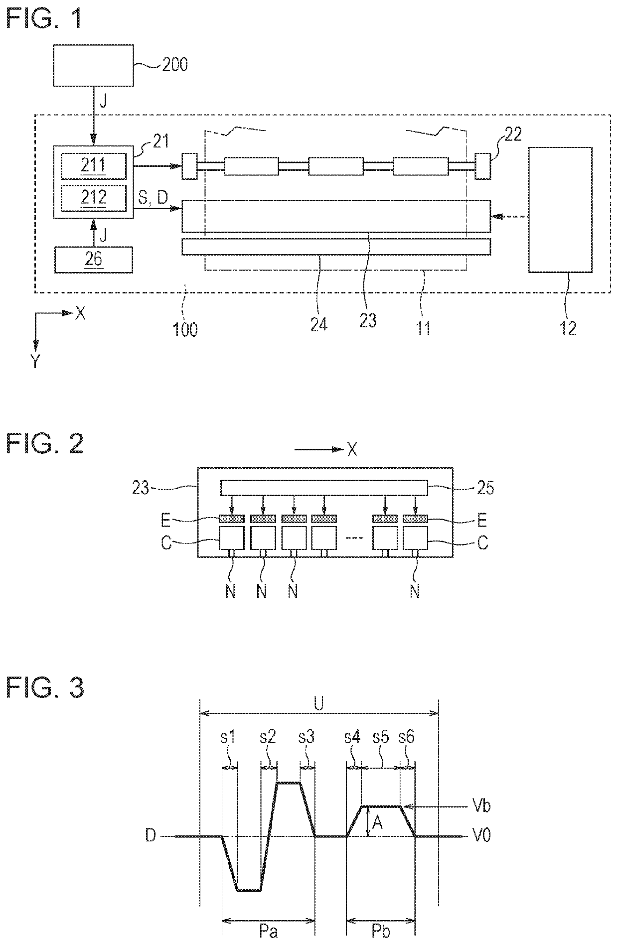
[0020]FIG. 1 is a block diagram illustrating a configuration of a liquid ejecting apparatus 100 according to a first embodiment. The liquid ejecting apparatus 100 of the first embodiment is an ink jet print apparatus ejecting droplets of ink which is an example of liquid to a medium 11. The medium 11 is a printing sheet, for example. Note that a printing target of an arbitrary material, such as a resin film or fabric, may be used as the medium 11. The liquid ejecting apparatus 100 includes a liquid container 12. The liquid container 12 stores ink. It is assumed here that a cartridge detachable from the liquid ejecting apparatus 100, a bag-like ink pack formed of a flexible film, or an ink tank which may be refilled with ink is used as the liquid container 12. Note that an arbitrary number of types of ink are stored in the liquid container 12.
[0021]An external apparatus 200 is coupled to the liquid ejecting apparatus 100 in a wired or wireless manner. The external ...
second embodiment
B: Second Embodiment
[0063]A second embodiment will be described. In modes illustrated hereinafter, components having functions the same as those of the first embodiment are denoted by reference numerals the same as those of the first embodiment and detailed descriptions thereof are omitted where appropriate.
[0064]A control unit 21 of the second embodiment selects one of a plurality of operation modes including operation modes A to C. Specifically, the control unit 21 selects one of the plurality of operation modes in accordance with an instruction issued by a user using an external apparatus 200 or an operation device 26. The control unit 21 causes a liquid ejecting head 23 to execute an operation corresponding to the selected operation mode.
[0065]In the operation mode A, a maximum value of strength of micro vibration is a strength VH. When the operation mode A is selected, the control unit 21 controls the liquid ejecting head 23 similarly to the first embodiment. Specifically, when...
third embodiment
C: Third Embodiment
[0071]A plurality of print jobs J are successively supplied from an external apparatus 200 or an operation device 26 to a control unit 21. In the third embodiment, a first print job J1 and a second print job J2 which are successively supplied from the external apparatus 200 or the operation device 26 are focused. The print job J2 is one of the print jobs J which is input immediately after the first print job J1. The second print job J2 is supplied from the external apparatus 200 or the operation device 26 to the control unit 21 before termination of a print operation performed on the first print job J1.
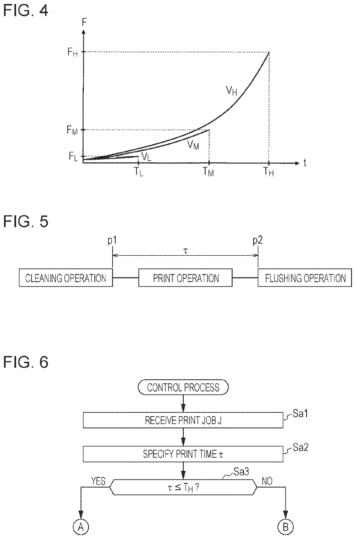
[0072]As described with reference to FIG. 4, a limit time T in which nozzles N reach an ejection limit varies depending on strength of micro vibration. Then a maintenance operation is not executed until the limit time T has elapsed, and the print operation using the micro vibration of strength corresponding to the limit period T may be continued.
[0073]On the other h...
PUM
 Abstract
Description
Claims
Application Information
 - R&D
- Intellectual Property
- Life Sciences
- Materials
- Tech Scout
- Unparalleled Data Quality
- Higher Quality Content
- 60% Fewer Hallucinations
Browse by: Latest US Patents, China's latest patents, Technical Efficacy Thesaurus, Application Domain, Technology Topic, Popular Technical Reports.
© 2025 PatSnap. All rights reserved.Legal|Privacy policy|Modern Slavery Act Transparency Statement|Sitemap|About US| Contact US: help@patsnap.com