Supporting assembly

a technology of supporting assembly and supporting rod, which is applied in the direction of casing/cabinet/drawer details, casing/cabinet/drawer details of electric apparatus, instruments, etc., can solve the problems of ineffective protection of in-vehicle computer or server from vibration damage, up and down vibrations to the vehicle, etc., so as to effectively mitigate the vibrations transferred to the casing of the electronic device.

Active Publication Date: 2022-05-17
INVENTEC PUDONG TECH CORPOARTION +1
View PDF5 Cites 2 Cited by
  • Summary
  • Abstract
  • Description
  • Claims
  • Application Information

AI Technical Summary

Benefits of technology

[0005]The invention is to provide a supporting assembly capable of effectively reducing the vibrations transferred to the electronic device supported by the supporting assembly.
[0008]According to the supporting assembly disclosed by the above embodiments, the plate body of the supporting assembly is fixed to the casing of the electronic device via the cushioning component and the fastener while the cushioning component is compressed between the casing and the fastener. Thus, the cushioning component can effectively absorb the vibrations transferred to the fastener from the casing of the electronic device. As a result, the vibrations transferred to the casing of the electronic device can be effectively mitigated.

Problems solved by technology

Travelling on uneven or bumpy road surfaces easily causes up-and-down vibrations to the vehicle.
However, the typical mount for in-vehicle computer or server only has a limited ability to absorb such vibrations, and therefore is unable to effectively protect the in-vehicle computer or server from vibration damage.

Method used


Image

  • Supporting assembly
  • Supporting assembly
  • Supporting assembly

Examples


first embodiment

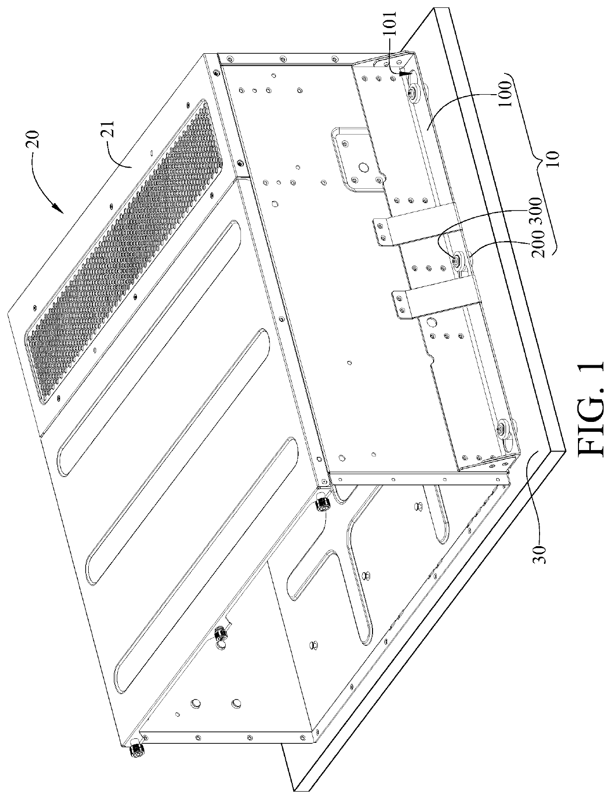
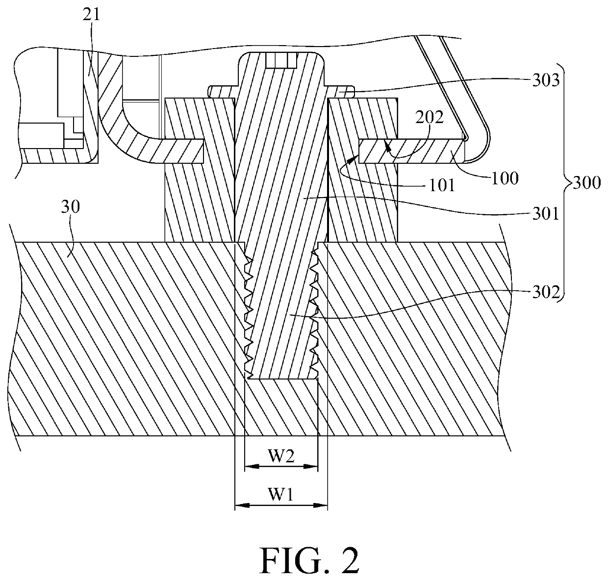
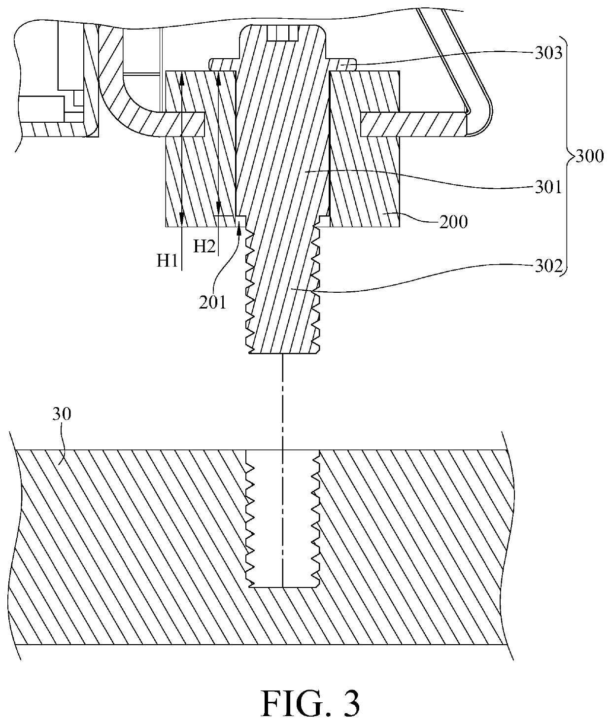
[0016]Please refer to FIG. 1 to FIG. 3, where FIG. 1 is a perspective view showing that a casing 21 of an electronic device 20 is mounted on a supporting assembly 10 according to the invention, FIG. 2 is a partially enlarged side cross-sectional view of the supporting assembly 10 and the casing 21 of the electronic device 20 in FIG. 1, and FIG. 3 is a side cross-sectional view showing that a cushioning component 200 of the supporting assembly 10 in FIG. 2 is not deformed.

[0017]The supporting assembly 10 is configured to be mounted on a side of the casing 21 of the electronic device 20 so as to fix the casing 21 to a chassis 30; in other words, the supporting assembly 10 is configured for installing the electronic device 20 to the chassis 30. In this embodiment, the supporting assembly 10 includes a plate body 100, a plurality of cushioning components 200, and a plurality of fasteners 300. In this embodiment, the electronic device 20 is, for example, an automotive computer or an in-v...

second embodiment

[0026]Note that the above configuration of the cushioning component 200 and connection between the cushioning component 200 and the chassis 30 are exemplary and not intended to limit the invention. For example, please refer to FIG. 4 and FIG. 5, where FIG. 4 is a partially enlarged side cross-sectional view of a supporting assembly 10a and a casing 21a of an electronic device 20a, and FIG. 5 is a side cross-sectional view showing that a cushioning component 200a of the supporting assembly 10a in FIG. 4 is not deformed.

[0027]In this embodiment, the supporting assembly 10a includes a plate body 100a, the cushioning component 200a, a positioning pillar 400a and a fastener 300a. The plate body 100a includes a mounting hole 101a and is configured to be fixed to the casing 21a of the electronic device 20a.

[0028]In this embodiment, the cushioning component 200a is a two-piece structure. In detail, the cushioning component 200a includes a first cushioning component 210a and a second cushi...


PUM


Abstract

A supporting assembly configured to fix a casing of an electronic device to a chassis and including a plate body, a cushioning component and a fastener. The plate body includes a mounting hole. The cushioning component is disposed through the mounting hole. The cushioning component includes a through hole. The fastener is disposed through the through hole of the cushioning component. A side of the fastener is configured to be fixed to the chassis, and the cushioning component is compressed by another side of the fastener and the chassis.

Description

CROSS-REFERENCE TO RELATED APPLICATIONS[0001]This non-provisional application claims priority under 35 U.S.C. § 119(a) on Patent Application No(s). 202010507181.2 filed in China, on Jun. 5, 2020, the entire contents of which are hereby incorporated by reference.BACKGROUND OF THE INVENTIONTechnical Field of the Invention[0002]The invention relates to a supporting assembly, more particularly to a supporting assembly including a cushioning component.Description of the Related Art[0003]Travelling on uneven or bumpy road surfaces easily causes up-and-down vibrations to the vehicle. For the vehicles having an in-vehicle computer or server, such vibrations will be transmitted to the in-vehicle computer or server through the mount fixed thereto.[0004]However, the typical mount for in-vehicle computer or server only has a limited ability to absorb such vibrations, and therefore is unable to effectively protect the in-vehicle computer or server from vibration damage.SUMMARY OF THE INVENTION[0...

Claims


Application Information

Patent Timeline
Patent Type & Authority Patents(United States)
IPC IPC(8): H05K5/02B60R16/023H05K5/00H05K5/06
CPCB60R16/0239H05K5/0008H05K5/0204H05K5/0247H05K5/069B60R11/02F16F15/02G06F1/182B60R2011/0036B60R2011/0052H05K7/1412
Inventor HSIAO, CHI-CHENGPENG, YING-CHAOYANG, CHUN-YING
Owner INVENTEC PUDONG TECH CORPOARTION
Why Eureka
Try Eureka