

Disk recording/reading apparatus
- Summary
- Abstract
- Description
- Claims
- Application Information
AI Technical Summary
Benefits of technology
Problems solved by technology
Method used
Image

Examples
first embodiment
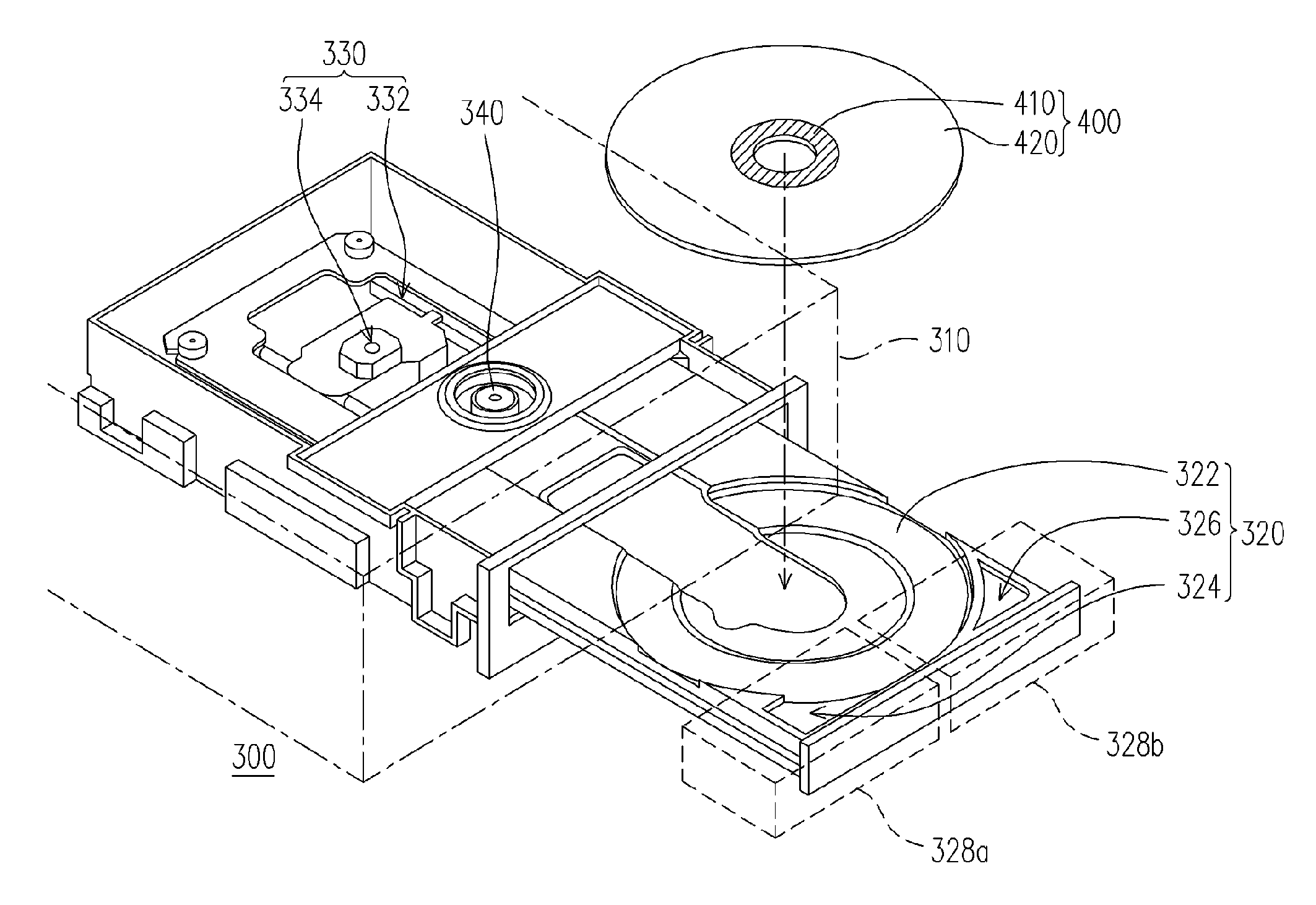
[0029]FIG. 3A is a schematic structure diagram of a disk recording / reading apparatus according to the first embodiment of the present invention. Referring to FIG. 3A, the disk recording / reading apparatus 300 in the embodiment is, for example, an optical disk drive, a disk burner, a DVD ( digital versatile disc) player or a DVD burner and used for recording / reading a disk 400. The disk 400 includes a hub (clamping area) 410 and a data area 420. The data area 420 is located at a region outside the hub 410, and the disk 400 spins around the center of the hub 410. The disk recording / reading apparatus 300 includes a case 310, a tray 320, an optical pickup unit (OPU) 330 and a clamping element 340, wherein the tray 320, the OPU 330 and the clamping element 340 are disposed inside the case 310.
[0030] The tray 320 has a concave trough 322, a concave trough extension portion 324 and an airflow guiding opening 326. The concave trough 322 is used for placing the disk 400. The front region of ...
second embodiment
[0038]FIG. 4A is a schematic structure diagram of a disk recording / reading apparatus according to the second embodiment of the present invention. FIG. 4B is a top view of the disk recording / reading apparatus in FIG. 4A in operation. FIG. 4C is a cross-sectional view along plane A-B of the disk recording / reading apparatus in FIG. 4B in operation. Referring to FIGS. 4A-4C, the disk recording / reading apparatus 500 of the embodiment is similar to the disk recording / reading apparatus 300 in the first embodiment, except for a unique feature that in the disk recording / reading apparatus 500 of the embodiment, there is no airflow guiding opening 326. The tray 520 of the disk recording / reading apparatus 500 has a concave trough 522 and a concave trough extension portion 524. The front region of the tray 520 and beyond the concave trough 522 is divided into a first front end 528a and a second front end 528b. In the embodiment, the concave trough extension portion 524 stretches from the concave...
PUM
 Abstract
Description
Claims
Application Information