Tripod constant-velocity joint

Inactive Publication Date: 2019-02-21
ERAE AMS CO LTD
View PDF0 Cites 0 Cited by
  • Summary
  • Abstract
  • Description
  • Claims
  • Application Information

AI Technical Summary

Benefits of technology

[0014]According to the present invention, since the outer roller is elastically supported outwardly in a radial direction with respect to the inner roller, a clearance bet

Problems solved by technology

In such a tripod constant velocity joint, vibration and noise may occur due to a clearance between the roller assembly and the housing.
In particul

Method used


Image

  • Tripod constant-velocity joint
  • Tripod constant-velocity joint
  • Tripod constant-velocity joint

Examples


Embodiment Construction

Technical Problem

[0007]The present invention has been made in an effort to provide a tripod constant velocity joint which can reduce a vibration and a noise which may occur due a clearance between a roller assembly and a housing.

Technical Solution

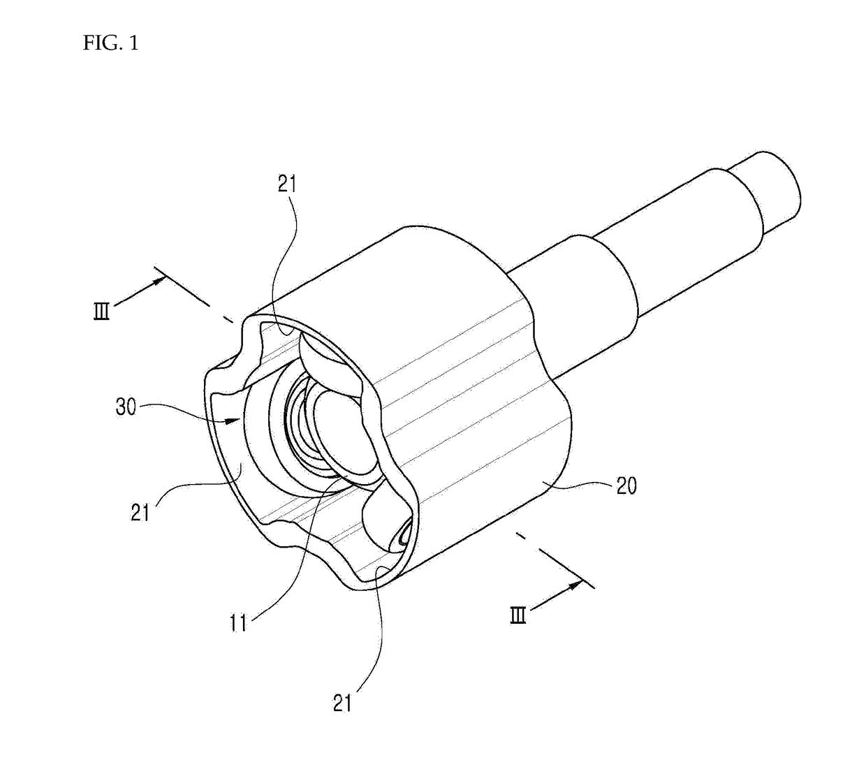
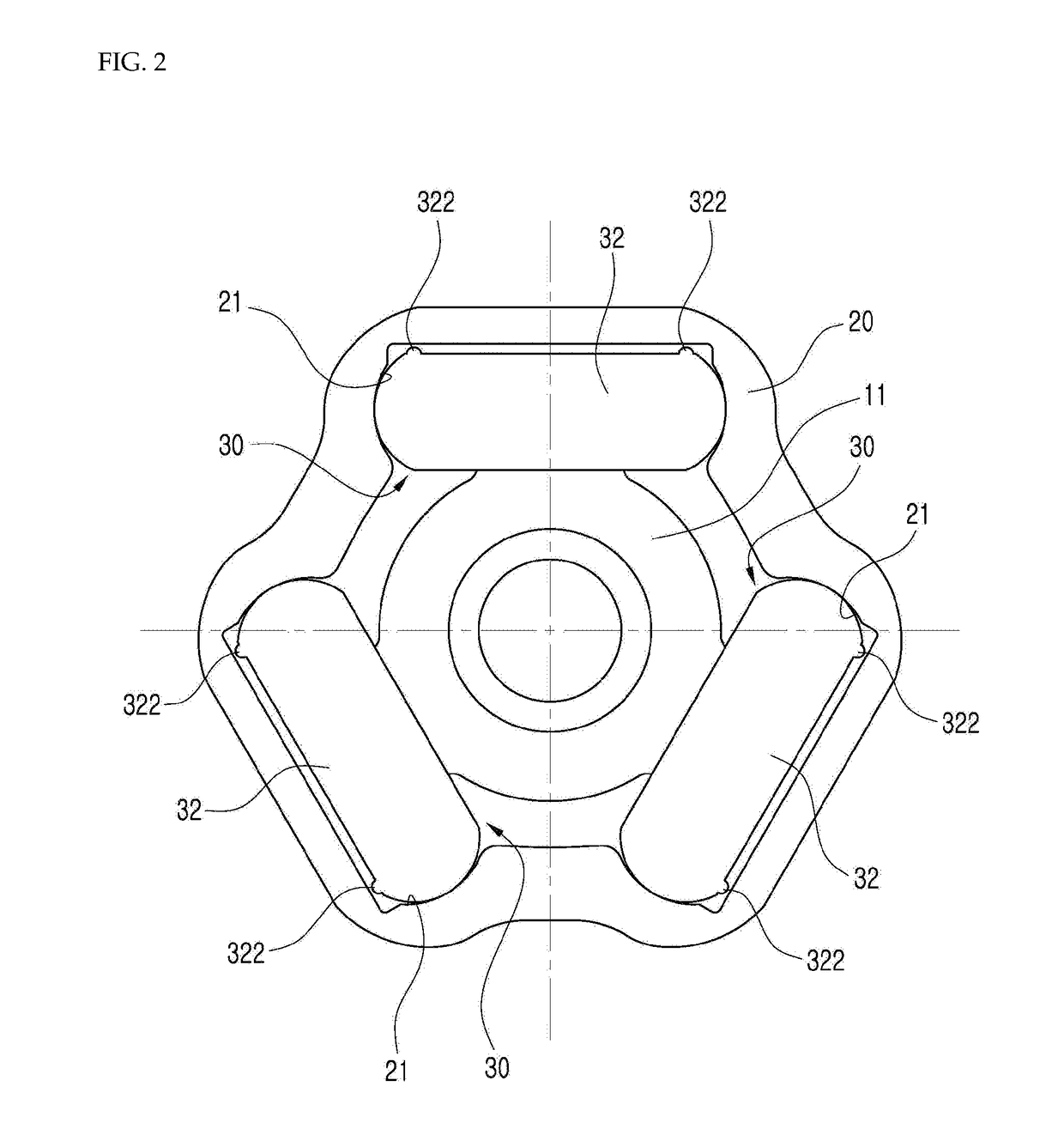
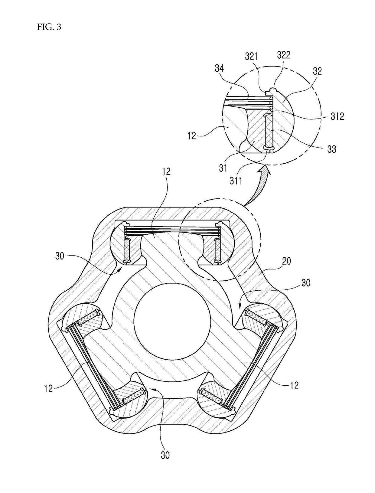
[0008]A tripod constant velocity joint according to an embodiment of the present invention includes: a spider having a plurality of trunnions; a plurality of roller assemblies which are respectively assembled to the plurality of the trunnions; and a housing defining a plurality of track grooves which respectively receive the plurality of roller assemblies. The respective roller assembly includes: an inner roller which is coupled to the trunnion; an outer roller which is disposed to surround the inner roller; a needle roller which is interposed between the inner roller and the outer roller; and an elastic member which elastically supports the outer roller outwardly in a radial direction with respect to the inner roller.

[0009]The inner roller...


PUM


Abstract

A tripod constant velocity joint includes: a spider having a plurality of trunnions; a plurality of roller assemblies which are respectively assembled to the plurality of the trunnions; and a housing defining a plurality of track grooves which respectively receive the plurality of roller assemblies. The respective roller assembly includes: an inner roller which is coupled to the trunnion; an outer roller which is disposed to surround the inner roller; a needle roller which is interposed between the inner roller and the outer roller; and an elastic member which elastically supports the outer roller outwardly in a radial direction with respect to the inner roller.

Description

TECHNICAL FIELD[0001]The present invention relates to a tripod constant velocity joint for vehicles.BACKGROUND ART[0002]A drive shaft assembly is interposed between a transmission and a driving wheel of a vehicle to transmit a driving force.[0003]The drive shaft assembly includes a drive shaft and two constant velocity joints which are respectively disposed on both ends thereof. The constant velocity joint which is disposed at a side toward the transmission is called an inboard joint and the constant velocity joint which is disposed at a side toward the driving wheel is called an outboard joint, and a tripod constant velocity joint which allows an axial displacement is generally used as the inboard constant velocity joint.[0004]The tripod constant velocity joint includes a spider having three trunnions, roller assemblies which are respectively assembled to the trunnions, and a housing which receives the roller assemblies.[0005]Various roller assemblies of different structures have b...

Claims


Application Information

Patent Timeline
IPC IPC(8): F16D3/205F16D3/223
CPCF16D3/2055F16D3/223F16D2003/2026F16D2003/22303F16D2003/22309F16D3/205F16D3/22Y10S464/905
Inventor LEE, YOUNG-DOOLEE, HYUN-ILJEONG, JAE-SEUNGLEE, JANG-SUN
Owner ERAE AMS CO LTD
Why Eureka
Try Eureka