Roll mount device for vehicle

a technology for vehicles and mounting devices, applied in vehicle sub-unit features, jet propulsion mounting, spring/damper functional characteristics, etc., can solve the problems of difficult to improve the complexity of vibration and noise generated in an actual vehicle, and the booming noise generated in a specific frequency band, so as to improve the complexity of vibration and noise generated in a vehicle. , the effect of reducing vibration and nois

Active Publication Date: 2020-12-10
HYUNDAI MOTOR CO LTD +1
View PDF0 Cites 1 Cited by
  • Summary
  • Abstract
  • Description
  • Claims
  • Application Information

AI Technical Summary

Benefits of technology

[0007]The present disclosure has been made in an effort to solve the above-described problems associated with the prior art, and an object of the present disclosure is to provide a roll mount device for a vehicle capable of effectively reducing vibration and noise generated in various frequency bands, thereby improving complicated vibration and noise generated in a vehicle.

Problems solved by technology

The conventional roll mount device has a simple shape and has a large amount of rubber used, which are advantageous for improving vibration and noise (NVH: noise, vibration, harshness) and strength, but has a drawback that it is difficult to improve complicated vibration and noise generated in an actual vehicle, in particular, booming noise generated in a specific frequency band.

Method used


Image

  • Roll mount device for vehicle
  • Roll mount device for vehicle
  • Roll mount device for vehicle

Examples


Embodiment Construction

[0021]Hereinafter, reference will now be made in detail to various embodiments of the present disclosure, examples of which are illustrated in the accompanying drawings and described below. While the disclosure will be described in conjunction with exemplary embodiments, it will be understood that present description is not intended to limit the disclosure to those exemplary embodiments. On the contrary, the disclosure is intended to cover not only the exemplary embodiments, but also various alternatives, modifications, equivalents and other embodiments, which may be included within the spirit and scope of the disclosure as defined by the appended claims.

[0022]Hereinafter, the present disclosure will be described so that those skilled in the art can easily implement the present disclosure.

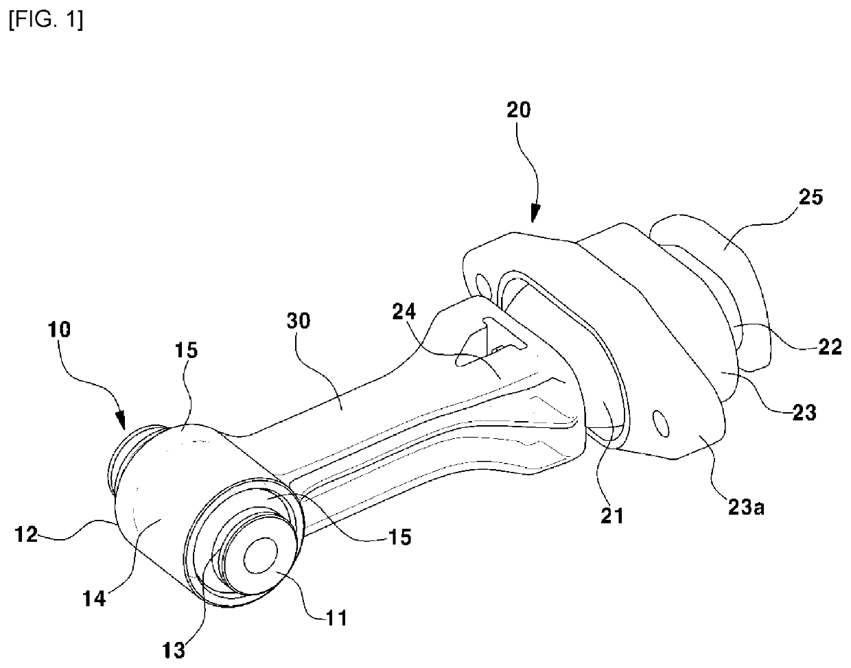
[0023]As illustrated in FIG. 1, a roll mount device of the present disclosure may include a front mount 10 to be coupled to a power train, a rear mount 20 to be coupled to a vehicle body, and a rod...


PUM


Abstract

A roll mount device for a vehicle includes: a front mount configured to be connected to a power train; a rear mount configured to be connected to a vehicle body; and a rod disposed between the front mount and the rear mount. The front mount comprises: a core configured to be connected to the power train to receive vibration transmitted from the power train; an outer pipe disposed outside the core and spaced from the core by a predetermined distance with respect to a radial direction of the core; an elastic body disposed between the core and the outer pipe to absorb vibration transmitted thereto from the core; and a stopper disposed on an outer surface of the core to be spaced from an inner surface of the outer pipe by a predetermined distance.

Description

CROSS-REFERENCE TO RELATED APPLICATION[0001]This application claims the benefit of priority to Korean Patent Application No. 10-2019-0067831 filed on Jun. 10, 2019, the entire contents of which are incorporated herein by reference.TECHNICAL FIELD[0002]The present disclosure relates to a roll mount device for a vehicle, and more particularly, to a roll mount device configured to improve vibration and noise performance of a vehicle.BACKGROUND[0003]Generally, a vehicle has employed an engine mounting system to reduce vibration and noise transmitted from a power train to a vehicle body, and the engine mounting system is classified into an inertial three-point support type and an inertial four-point support type. In the inertial three-point support type mounting system, a rod type roll mount device is applied to a lower end of the power train.[0004]A conventional rod-type roll mount device has employed a dog bone-type roll rod in order to effectively control behavior of the power train a...

Claims


Application Information

Patent Timeline
Patent Type & Authority Applications(United States)
IPC IPC(8): B60K5/12F16F15/04
CPCB60K5/1241F16F15/04B60K5/1291B60K5/1208B60K5/1233F16F2228/06F16F2228/14F16F1/3863F16F1/3835F16F1/3828B60Y2306/09
Inventor KIM, YONG JOO
Owner HYUNDAI MOTOR CO LTD
Why Eureka
Try Eureka