Fan speed control circuit

a technology of speed control circuit and fan motor, which is applied in the direction of electric controller, motor/generator/converter stopper, dynamo-electric converter control, etc., can solve the problems of high output ripple, vibration, and inability to precisely position the rotor, so as to achieve a considerable reduction of vibration and noise in the fan motor

a technology of speed control circuit and fan motor, which is applied in the direction of electric controller, motor/generator/converter stopper, dynamo-electric converter control, etc., can solve the problems of high output ripple, vibration, and inability to precisely position the rotor, so as to achieve a considerable reduction of vibration and noise in the fan motor

US7218846B2Active Publication Date: 2007-05-15DELTA ELECTRONICS INC

Image

  • Fan speed control circuit
  • Fan speed control circuit
  • Fan speed control circuit

Examples


Embodiment Construction

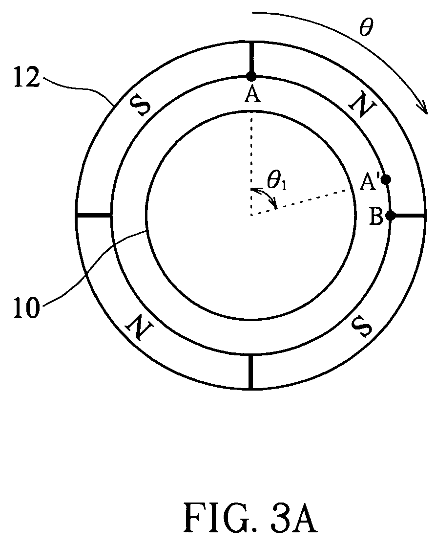
[0020]FIG. 3A is a schematic diagram illustrating the angular position of the rotor 12 relative to the stator 10 in a four-pole DC motor; FIG. 3B illustrates the current waveform of the four-pole DC motor shown in FIG. 3A during unloaded operations, wherein the horizontal axis shows the clockwise-rotating angle (angular position θ) of the rotor 12.

[0021]Comparing the relative angular position of the stator 10 and the rotor 12 in FIG. 3A with the current waveform in FIG. 3B, it can be seen that, for a four-pole motor, the current waveform abruptly changes due to the cogging torque when the rotor 12 rotates to angular positions near nπ / 2 (n=1, 2, 3 . . . ). For instance, after the rotor 12 starts to rotate clockwise from point A, the current waveform abruptly changes when the rotor 12 rotates to an angular position between θ1 (point A′) and π / 2 (point B), and the same is true with each of the other π / 2 periods. On the other hand, since the rotor 12 is divided into four magnetic region...


PUM


Abstract

A fan speed control circuit includes a pulse width modulation (PWM) signal generating circuit, a driving circuit and a phase compensation unit. The PWM signal generating circuit generates a PWM control signal with a sequence of alternating on-time and off-time, and the driving circuit outputs a driving signal according to the PWM control signal to a fan motor. The phase compensation unit is connected to the fan motor for delaying or advancing the PWM control signal by a phase angle to synchronize the acting period of the back electromotive force formed by the magnetic flux variation with the off-time of the PWM control signal.

Description

BACKGROUND OF THE INVENTION[0001](a) Field of the Invention[0002]The present invention relates to a fan speed control circuit and, more particularly, to a fan speed control circuit capable of reducing vibrations and noises in a fan motor by using a phase control method.[0003](b) Description of the Related Art[0004]Among conventional fan speed control technologies, pulse width modulation (PWM) control is the most common method used to control the speed of direct current (DC) motors.[0005]Referring to FIG. 1, in a conventional PWM control method, an external PWM signal 102 is used to drive a bipolar transistor 104 and a driver IC 106 such that the terminal voltage of a stator coil 108 is controlled. Also, a hall element 110 whose output voltage is directly proportional to the magnetic field strength is used to sense the magnetic polarity of the rotor in a fan motor.[0006]Referring to FIG. 2, the fan motor is “on-time” as the pulse level of the incoming PWM signal 102 is high (also cal...

Claims


Application Information

Patent Timeline
15 May 2007
Publication
US7218846B2
IPC
H02P7/29
CPC
H02P7/29
Inventors
WU, CHIA-FENG; HSIEH, CHING-SEN