Unimpeded distalizing jig

a distalizing jig and unobstructed technology, applied in the field of orthodontic appliances for distalizing molars, can solve the problems of irritation or reaction, appliance has a limited range of displacement, and has lost favor with orthodontists

Active Publication Date: 2022-07-26
SURIANO ANTHONY T +1
View PDF229 Cites 0 Cited by
  • Summary
  • Abstract
  • Description
  • Claims
  • Application Information

AI Technical Summary

Benefits of technology

[0012]The unimpeded distalizing jig has been designed for segmental distalization with the ultimate intent of improving the interdigitation between opposing dental arches and to create additional intra-arch space to adequately deliver and align the permanent teeth.
[0013]This design, is a substantial improvement over the Carriere Motion 3D, U.S. Pat. No. 7,985,070, FIGS. 3-5, expressly incorporated herein by reference in its entirety. The present design allows for instant modification in size to be made in the operatory setting, and allows the transference of applied forces without the hindrance or resistance intimately associated with the anterior stabilizing unit as in the prior art design. This enhancement focuses the generated orthodontic forces to the intended dental-unit benefactor(s) without the inherent frictional impedance that the prior art is dependent on, in order to maintain stability in its fixation.
[0015]The present invention provides a telescoping structure, with a distalizing force preferably generated by an inter-dental arch elastic element. The sagittal vector of force is inappreciably sustained by a bondable attachment to a selected anterior stabilizing dental unit, e.g., a canine tooth, therein delegating the applied distalizing force to the posterior, intra-dental fixation point located on the molar benefactor. The telescoping structure is preferably curved, which achieves two purposes: first, it provides appropriate clearance over a range of applications, and thus minimizes the need for an orthodontist to inventory multiple appliances (the length of the rod may be adjusted in-procedure).
[0019]In some cases, it is desired to apply only a horizontal force to the molar, and therefore instead of a universal joint fixation, the posterior fixation may be a horizontal rotatable pivot. In other cases, the rotation of the distalizing molar is desired to be greater than the radius of curvature of the rod, and this may be achieved by providing a vertical rotatable constrained pivot, with the rotational moment dependent on the distalization extent and the distance of the vertical rotatable pivot from the molar central axis. Typically, use of a rigid joint on the molar fixation is undesired, in that it complicates installation without substantial benefit.

Problems solved by technology

For example, the once highly utilized headgear appliance, intended to generate additional space and / or orthopedically influence skeletal balance and symmetry between the opposing jaws, has lost favor with orthodontists because of the requisite wear-time commitments coupled with the frustrating inability to cultivate patient compliance to fulfill those desired objectives.
Further, the appliance has a limited range of displacement, and in some cases, the appliance need be replaced with another to create the desired extent of distalization.
In some cases, a patient may be nickel-sensitive, and therefore the appliance could cause irritation or reaction.

Method used


Image

  • Unimpeded distalizing jig
  • Unimpeded distalizing jig
  • Unimpeded distalizing jig

Examples


Embodiment Construction

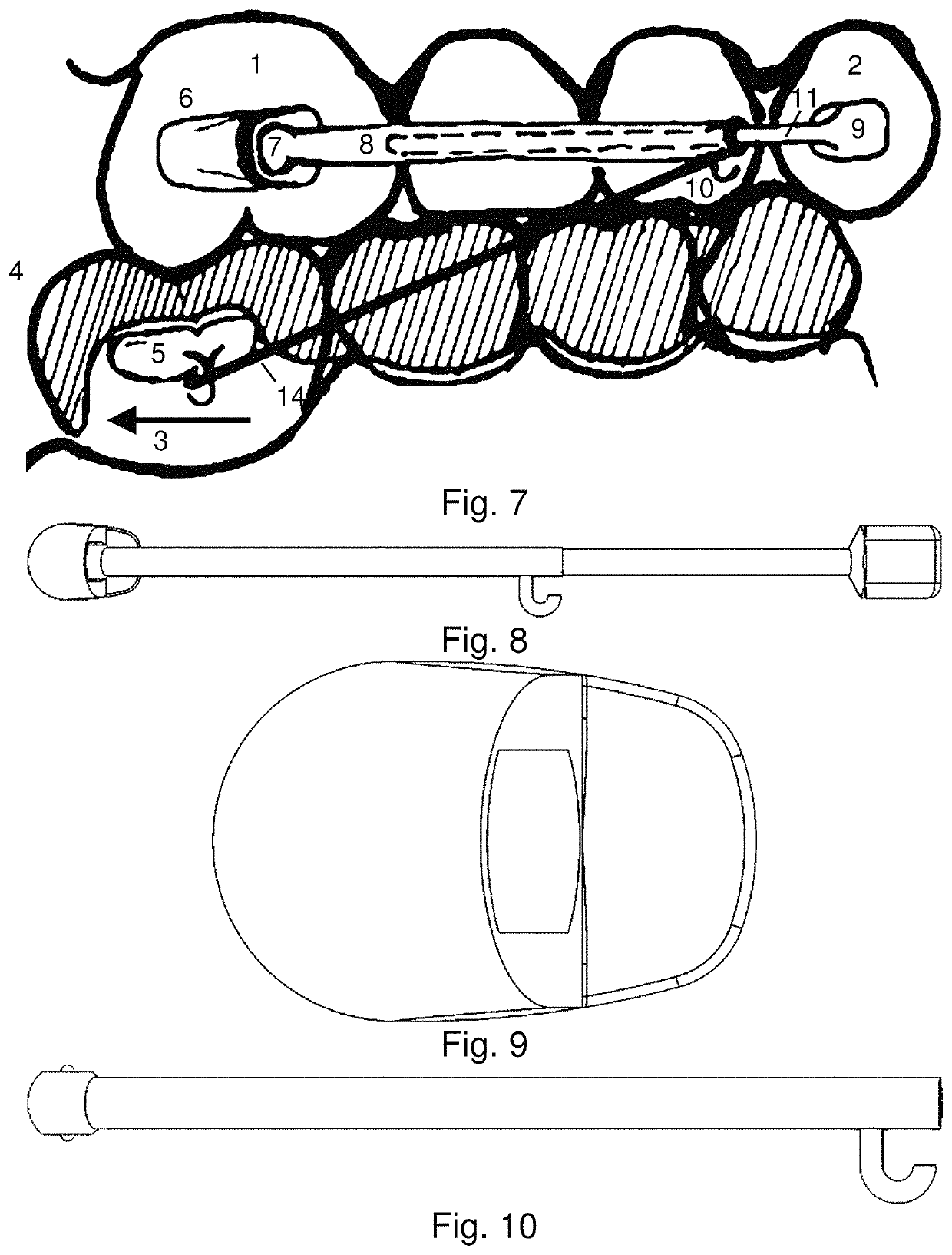
[0046]The unimpeded distalizing jig according to the present invention, as depicted in FIG. 7, has three components.

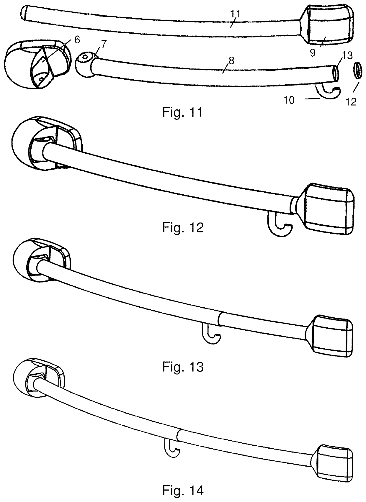
[0047]FIG. 7 shows an embodiment of the invention in a use configuration. The first component, also as shown in FIG. 9 is a bondable pad 6 that is attached to, e.g., the labial surface of the first permanent molar 1. The bondable pad 6 has a recess to receive an end 7 of the second component, which is a cylindrical-tube 8 also shown in FIG. 10, that can rotate within the bondable pad 6, akin to a ball-in-socket joint. The cylindrical-tube 8 allows for the introduction of the third component, which is a rod-like structure 11, also shown in FIGS. 11-14, which has on its end opposite the ball 7 another bondable pad 9 that can be bonded or secured to the anterior stabilizing unit 2. An elastic band 14 retaining attachment pad 5 is bonded to a tooth, e.g., a molar on the other dental arch. An anchor unit 4 is established by providing a mechanical construct, such as a custom...


PUM


Abstract

An unimpeded distalizing jig, comprising a pair of tooth bond pads, an intra dental arch telescoping assembly, comprising a rod-like insertion and a tubular shell, which constrains the rod-like insertion to move with respect to the tubular shell along an elongated axis, which may be a radial path; and a force generating structure configured to supply an off-axis distalizing force to the intra dental arch telescoping assembly, such that the distalizing force is provided to the posterior tooth substantially without applying an anteriorizing force on the anterior tooth. The force generating structure may be an elastic band fixed by a hook to the tubular shell on one side, and to a molar on an opposing dental arch on the other side.

Description

CROSS REFERENCE TO RELATED APPLICATIONS[0001]The present application is a non-provisional of U.S. Provisional Patent Application No. 62 / 771,495, filed Nov. 26, 2018, which is expressly incorporated herein by reference in its entirety.FIELD OF THE INVENTION[0002]The present invention relates to an orthodontic appliance for distalizing molars.BACKGROUND OF THE INVENTION[0003]Patient compliance is the one treatment variable that orthodontists historically have had, and currently still have, the least control over, and yet it remains a significant factor in treatment success and the time required to realize those assigned treatment objectives. There remains an unrelenting need to create or modify orthodontic appliances that would promote a greater willingness of the patient to invest the necessary time and effort to satisfy the requisite compliance.[0004]For example, the once highly utilized headgear appliance, intended to generate additional space and / or orthopedically influence skelet...

Claims


Application Information

Patent Timeline
Patent Type & Authority Patents(United States)
IPC IPC(8): A61C7/36A61C7/10A61C7/14
CPCA61C7/14A61C7/10A61C7/36A61C7/08
Inventor SURIANO, ANTHONY TSURIANO, JUSTIN T.
Owner SURIANO ANTHONY T
Why Eureka
Try Eureka