Compressor having adjustment mechanism

a compressor and adjustment mechanism technology, applied in the direction of liquid fuel engine components, pump components, non-positive displacement fluid engines, etc., can solve the problems of increased power of internal combustion engines or fuel cells, reduced efficiency of low-volume flow through compressors within the compressor characteristic map, and inability to operate in a safe manner. , to achieve the effect of reducing inlet cross-section, reducing inlet cross-section, and cost-effective and simple production

Active Publication Date: 2022-08-02
BORGWARNER INC
View PDF2 Cites 0 Cited by
  • Summary
  • Abstract
  • Description
  • Claims
  • Application Information

AI Technical Summary

Benefits of technology

[0009]The compressor according to the invention for a charging device comprises a compressor housing, a compressor wheel and an adjustment device. The compressor housing has a compressor inlet having an inlet cross-section and a compressor outlet. The compressor wheel is arranged in the compressor housing and rotatably mounted along a compressor axis. The adjustment mechanism is arranged in front of the compressor wheel axially in the current direction. Furthermore, the adjustment mechanism can be shifted between a first position and a second position in order to change the inlet cross-section, such that the inlet cross-section can be changed between a maximum inlet cross-section and a reduced inlet cross-section. Here, the adjustment mechanism forms the reduced inlet cross-section, such that the reduced inlet cross-section is arranged eccentrically in relation to the compressor axis. As a result of the eccentric arrangement of the reduced inlet cross-section, current vortices emerging on a rear side (in the current direction) or an inner edge (radially inner edge) of the adjustment mechanism between the adjustment mechanism and the compressor wheel interact eccentrically with the compressor wheel. The eccentricity changes the strength and the detachment frequency of the current vortices in the peripheral direction and influences the frequency spectrum in a favourable manner. Thus, a more broadband noise development can be generated which can be perceived less intensively. As a result, the NVH behaviour can thus be improved.
[0011]In designs of the compressor that can be combined with any of the previous designs, in each case one bearing bore can be provided in the compressor housing or in a bearing ring for each aperture element. Here, the bearing bores can be arranged around the aperture axis along a bolt circle. In other words, this means that the bolt circle is arranged concentrically around the aperture axis. This design makes the cost-effective and simple production possible as a result of the eccentric provision of the bearing bores relative to the compressor axis (i.e. concentrically to the aperture axis). Alternatively or additionally, the aperture elements can be rotatably mounted between a first position and a second position. Here, the aperture elements are mounted rotatably in a respective bearing bore. In particular, the aperture elements can be rotatably mounted between the first and the second position via in each case one bearing pin. This means the aperture elements can be rotatably mounted in the bearing bore via the bearing pin. In other words, this means that the bearing pins can be rotatably mounted in the respective bearing bore. The bearing pins can be formed integrally with the respective aperture element or connected fixedly (by e.g. welding, pressing, screwing, etc.) to it. Alternatively or additionally, the adjustment mechanism can release the inlet cross-section in the first position of the aperture elements, such that the maximum inlet cross-section is formed. Alternatively or additionally, the adjustment mechanism can reduce the inlet cross-section in the second position of the aperture elements, such that the reduced inlet cross-section is formed. Expressed alternatively, this means that the aperture elements can form the reduced inlet cross-section.

Problems solved by technology

In turn, this leads to a power increase of the internal combustion engine or the fuel cell.
Depending on the size and shape of the compressor, the operation with low volume flows through the compressor within the compressor characteristic map may be less efficient.
If the surge limit is not reached, the operation is no longer possible in an operatively safe manner.
Known current modification devices, in particular adjustment mechanisms, lead to an impact on the current conditions in the compressor which often lead to unfavourable behaviour of the compressor in terms of noise, vibration and harshness (NVH behaviour).

Method used


Image

  • Compressor having adjustment mechanism
  • Compressor having adjustment mechanism
  • Compressor having adjustment mechanism

Examples


first embodiment

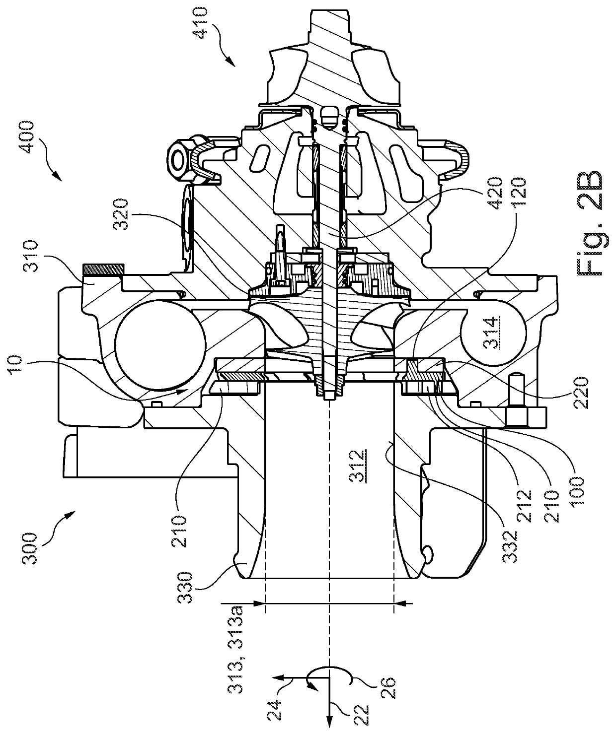
[0034] the adjustment ring 210 is arranged centrally (i.e. concentrically) around the aperture axis 102. The coupling circuit 214 is also arranged (concentrically) around the aperture axis 102 in the installed state. This is shown in FIG. 4A, which substantially corresponds to FIG. 3, yet in which the compressor inlet connecting piece 330 is not depicted, such that the adjustment ring 210 with the coupling recesses 212 along the coupling circuit 214 can be seen. When seen in relation to the adjustment ring 210, the coupling recesses 212 or the coupling circuit 214 are spaced apart with the same spacing from a radially inner periphery of the adjustment ring 210 (see FIG. 5A).

second embodiment

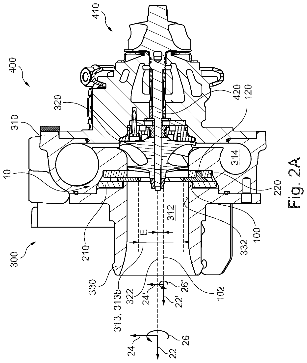
[0035]In comparison to this, the adjustment ring 210 is arranged centrally (i.e. concentrically) around the compressor axis 322. The coupling circuit 214 is here arranged (concentrically) around the aperture axis 102 in the installed state. This is shown in FIG. 4B which substantially corresponds to FIG. 3, yet in which the compressor inlet connecting piece 330 is not depicted, such that the adjustment ring 210 with the coupling recesses 212 along the coupling circuit 214 can be seen. Thus, the coupling circuit 214 with the coupling recesses 212 is arranged offset by the eccentricity E inside the adjustment ring 210. This means, when seen in relation to the adjustment ring 210, the coupling recesses 212 or the coupling circuit 214 are spaced apart from a radially inner periphery of the adjustment ring 210 at different spacings (see FIG. 5B).

[0036]As already mentioned, the aperture elements 100 each comprise a bearing pin 120 via which the aperture elements 100 are rotationally moun...


PUM


Abstract

A compressor for a charging device, and a charging device having a corresponding compressor. The compressor comprises a compressor housing having a compressor inlet and a compressor outlet, and a compressor wheel and an adjustment mechanism. The compressor wheel is arranged in the compressor housing and can be rotated along a compressor axis. The adjustment mechanism is arranged in front of the compressor wheel axially in the current direction and can be adjusted between a first position and a second position in order to change an inlet cross-section of the compressor inlet. As a result of the adjustability of the adjustment mechanism, the inlet cross-section can be changed between a maximum inlet cross-section and a reduced inlet cross-section. Here, the adjustment mechanism forms the reduced inlet cross-section in such a way that the reduced inlet cross-section is arranged eccentrically in relation to the compressor axis.

Description

CROSS-REFERENCE TO RELATED APPLICATIONS[0001]This application claims priority pursuant to 35 U.S.C. 119(a) of German Patent Application No. 102020102640.4, filed Feb. 3, 2020, which application is incorporated herein by reference in its entirety.TECHNICAL FIELD[0002]The present invention relates to a compressor having an adjustment mechanism. Furthermore, the invention relates to a charging device having such a compressor.BACKGROUND[0003]More and more vehicles of more recent generations are equipped with charging devices in order to achieve demand targets and legal requirements. When developing charging devices, it is important to optimise both the individual components and the system as a whole in terms of their reliability and efficiency.[0004]Known charging devices often have at least one compressor having a compressor wheel which is connected to a drive unit via a common shaft. The compressor compresses the fresh air suctioned for the internal combustion engine or for the fuel c...

Claims


Application Information

Patent Timeline
Patent Type & Authority Patents(United States)
IPC IPC(8): F04D29/66F04D29/42F04D29/053F02B37/10
CPCF04D29/667F04D29/053F04D29/4206F02B37/10F04D29/4213F04D29/464F02B39/10F02B37/22
Inventor KARSTADT, SASCHAWALKINGSHAW, JASONCOKSEN, AHMET
Owner BORGWARNER INC
Why Eureka
Try Eureka