Pressure-flushing system for a toilet bowl

Inactive Publication Date: 2019-10-31
SWISS AQUA TECH AG
View PDF0 Cites 3 Cited by
  • Summary
  • Abstract
  • Description
  • Claims
  • Application Information

AI Technical Summary

Benefits of technology

[0036]The advantages of an outflow module with simultaneous use of hydraulic gas accumulators according to the developed invention in a pressure flushing system for a toilet bowl are apparent from the effects which are recognizable solely externally: pressure wave flushing and low noise intensity during flushing. One essential advantage is the fact that the outflow module is universally usable in toilet pressure flushing devices; i.e., also advantageously in pressure flushing devices for various toilet bowl types of various producers. It is a simple, complete design which enables simple, rapid, and reliable mounting and simplifies the service. The service work relates in principle to the removal of the flushing water regulator, whereby the entire valve chamber becomes accessible. The outflow pipe is also accessible due to the removal of the DC

Problems solved by technology

These pressure flushing devices are not suitable for toilet bowls, because they are not capable without a water collection pressure device of dispensing a sufficient water quantity within a short time.
This system offers 2 L of water in three seconds, from which it is apparent that the initial water wave or the water front at the beginning of the water wave only flows out softly and does not have sufficient speed so that it is not sufficiently strong to reliably flush the toilet bowl.
One significant disadvantage of pressure flushing devices as they are described in the published American and French documents is the fact that after the valve the speed of the initial water outflow is

Method used


Image

  • Pressure-flushing system for a toilet bowl
  • Pressure-flushing system for a toilet bowl
  • Pressure-flushing system for a toilet bowl

Examples


Embodiment Construction

[0054]It is obvious that individual embodiments of the invention are to be illustrative and are not restrictive for technical solutions. A person skilled in the art will be able to find or establish many equivalents to the specific embodiments of the invention using no more than routine experiments. Such equivalents also fall under the patent claims.

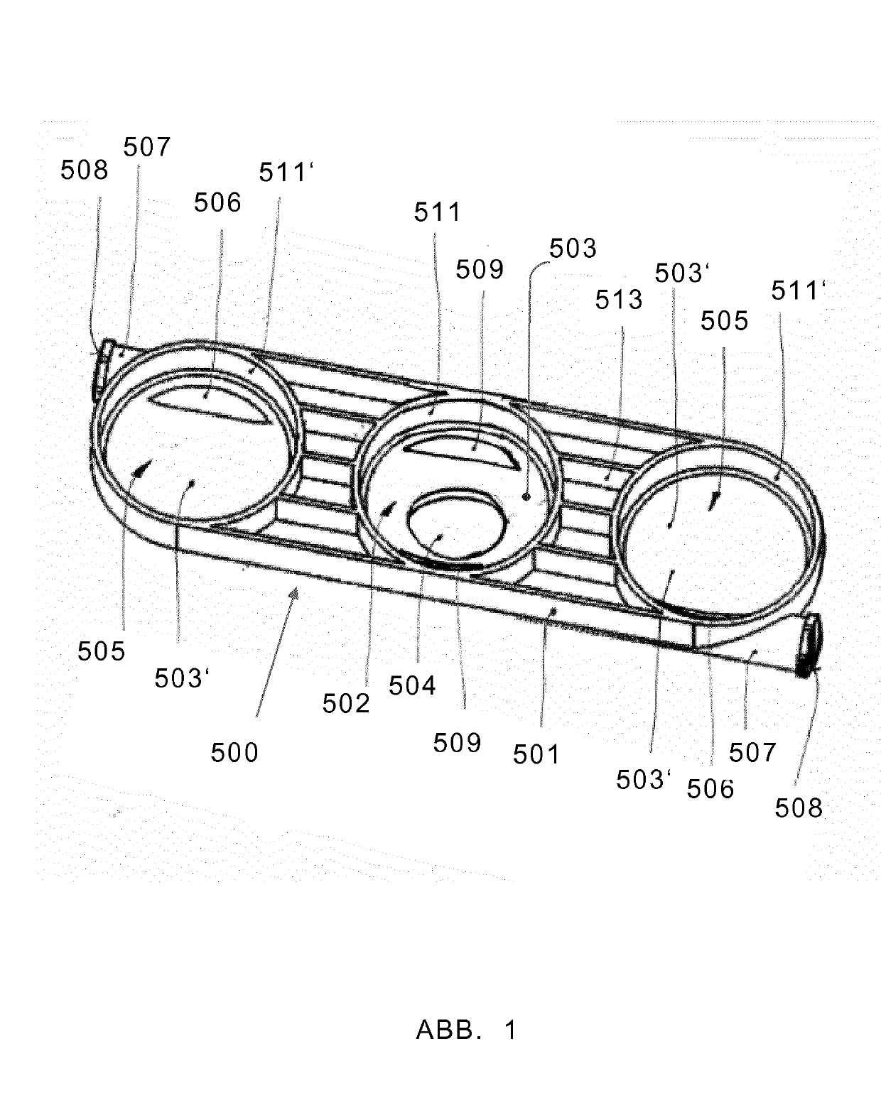
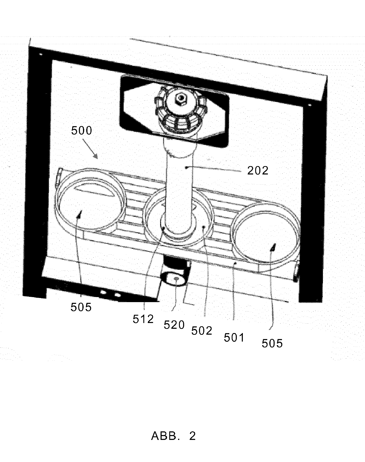
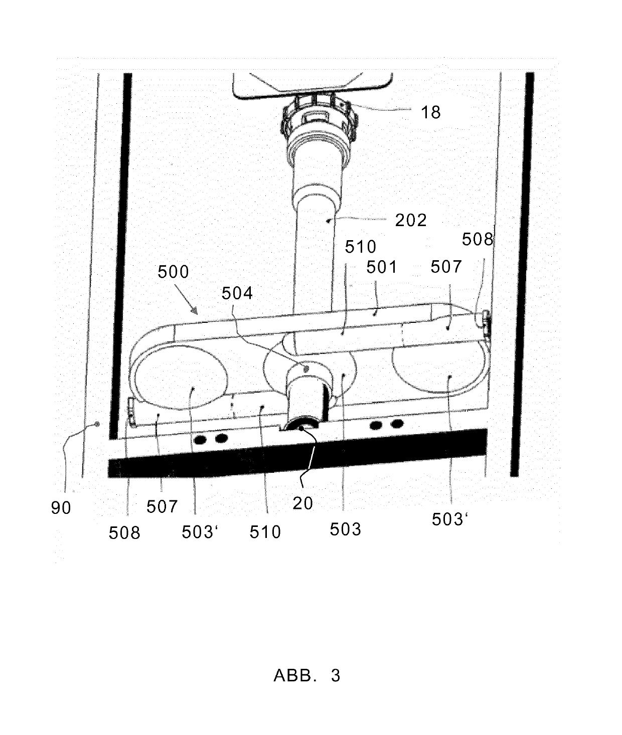
[0055]A specific embodiment of a cistern mounting 500 for a toilet water pressure flushing system 100 according to the invention using pressure wave flushing is shown in the example illustrated in FIGS. 1 to 3. The cistern mounting 500 for the toilet water pressure flushing system comprises a carrier plate 501 having a centrally arranged open outflow shell 502 accessible from above for accommodating an outflow module 200 (see FIG. 4), wherein the outflow shell 502 has an outflow opening 504 for the mounting of an outflow pipe 202 in its base 503 (FIG. 2). The carrier plate 501 furthermore has two open inflow shells 505 accessible from ab...


PUM


Abstract

The invention relates to a pressure-flushing system (100) for toilet bowls, comprising a cistern mounting (500) and a drain module (200), said drain module (200) comprising a vertically oriented pressurized water tank (501) and a drain pipe (502), a hydraulic drain valve (18) and a DC pipe interrupter (5). The drain pipe (502) is mounted vertically in the pressurized water tank (501) and projects from the bottom of the pressurized water tank (201) for a flow connection with the toilet bowl. The drain module (200) is retained by the cistern mounting (500), which also carries a gas accumulator (19). The cistern mounting (500) has a water-carrying design and has a water connection (8) for connection to a drinking water mains or similar, and connecting channels (507, 510) that fluidically connect the pressurized water tank (501) and the gas accumulator. The pressure-flushing system (100) complies with standard EN 1717, is compact and easy to install. It allows pressure-wave flushing with little water and low noise emission.

Description

FIELD OF THE INVENTION[0001]The invention belongs to the field of sanitary technology and hygiene devices. It relates to a pressure flushing system for a toilet bowl and in particular to a constructive solution for a cistern mounting of the toilet pressure flushing system and to a constructive solution for an outflow module of this pressure flushing system, wherein the pressure flushing system flushes using a pressurized water wave referred to as a shockwave. The pressure flushing system is designed so that the flushing takes place with little noise development and low water consumption, wherein the avoidance of contamination of the drinking water by backflow in the event of malfunctions in the water supply system is ensured. In the documents of this application, the term “pressure flushing container” for toilet flushes is to be understood in the meaning of a sanitary fitting for toilet bowls.BACKGROUND OF THE INVENTION[0002]Pressure flushing devices are typically known in the sanit...

Claims


Application Information

Patent Timeline
IPC IPC(8): E03D3/04E03D3/10
CPCE03D3/04E03D3/10
Inventor PANCURAK, FRANTISEK
Owner SWISS AQUA TECH AG
Why Eureka
Try Eureka