Image processing apparatus, image processing method, and storage medium

a technology of image processing and image, applied in the direction of matrix printers, visual presentation, instruments, etc., can solve the problems of image deterioration, image deterioration, density unevenness, and misalignment of print head printing positions,

Active Publication Date: 2022-08-02
CANON KK
View PDF3 Cites 0 Cited by
  • Summary
  • Abstract
  • Description
  • Claims
  • Application Information

AI Technical Summary

Benefits of technology

[0006]The present invention has been made in view of the above-described problem, so as to provide a technique capable of suppressing the data amount and suppressing density unevenness or the like which is caused by misalignment of the printing positions of nozzle groups in a case where ink of the same color is divided for multiple nozzle groups for printing.
[0025]According to the present invention, in a case where print data is divided for multiple nozzle groups that eject ink of the same color for printing, the data amount can be suppressed, and density unevenness or the like which is caused by misalignment of the printing positions of the nozzle groups can be suppressed.

Problems solved by technology

In a case where the same type of ink is divided for multiple print heads or nozzle groups for performing printing, there is a possibility that the printing positions of the print heads are misaligned due to a factor such as a difference in ink ejection speeds, a fluctuation in the postures of the print heads, a conveyance error of a print medium, or a correction error of a printing position.
In a case where such misalignment of the printing positions occurs, image deterioration such as density unevenness, streaks, or deterioration in graininess occurs in the printed image.
Therefore, the amount of intermediate product data is increased, the amount of data processed by the image processing part is increased, and a high-speed processing chip and a memory area are required, which result in cost increase.

Method used


Image

  • Image processing apparatus, image processing method, and storage medium
  • Image processing apparatus, image processing method, and storage medium
  • Image processing apparatus, image processing method, and storage medium

Examples


first embodiment

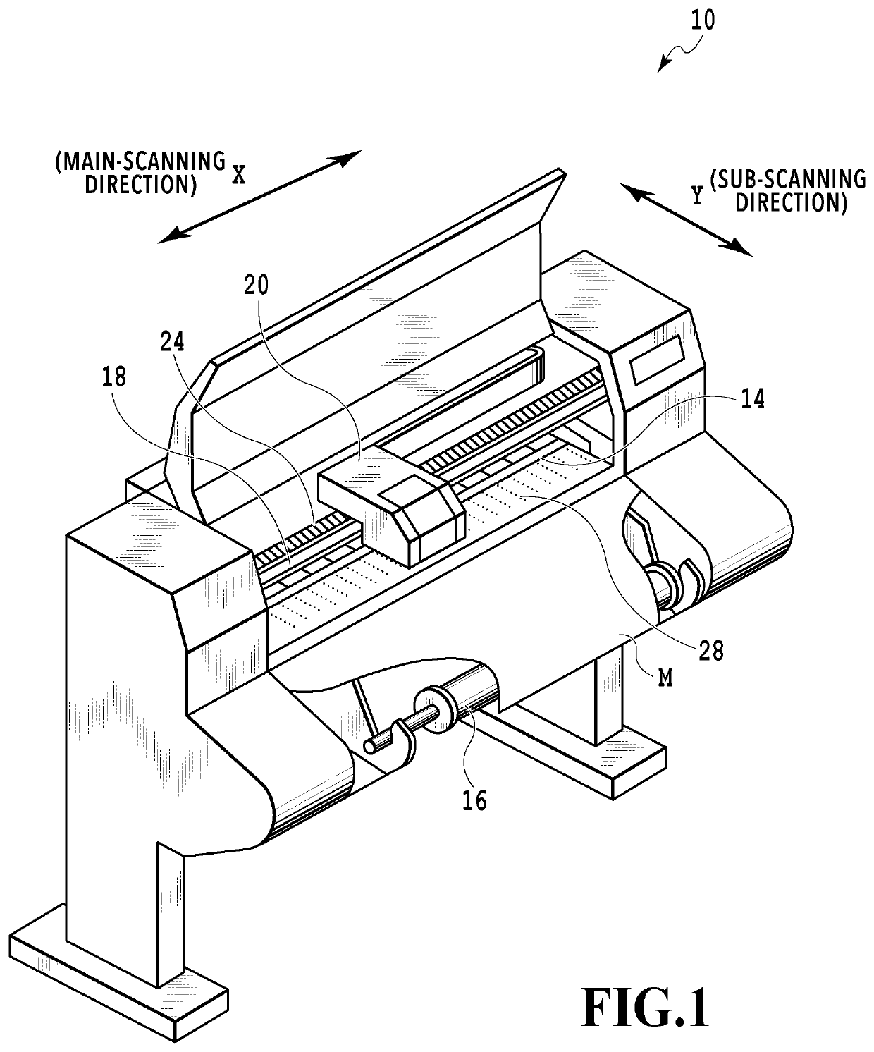
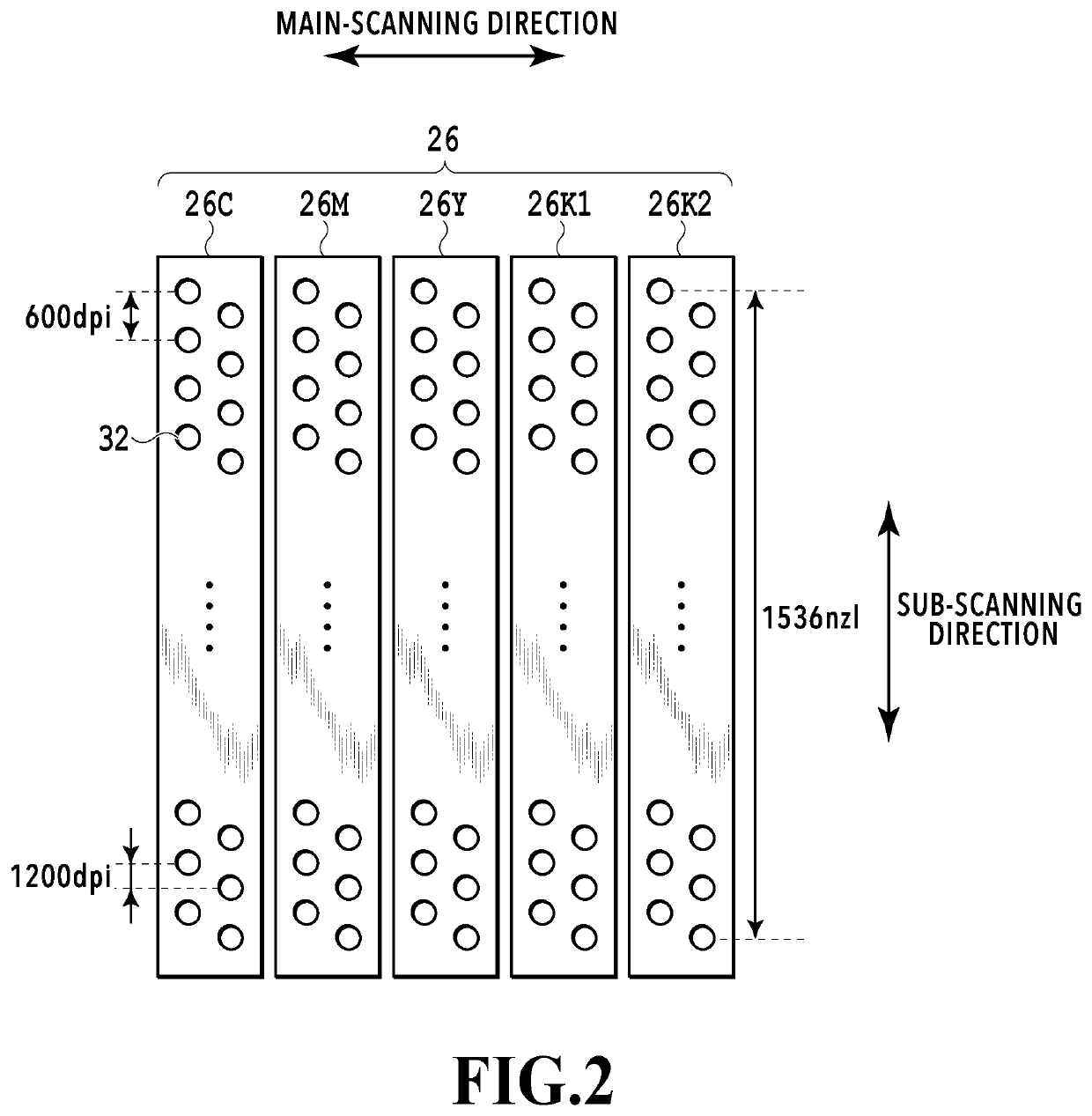
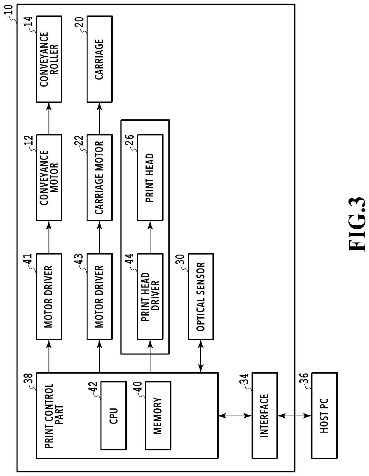
[0048]FIG. 1 is a schematic configuration diagram of a printing apparatus including an image processing apparatus according to the present embodiment. FIG. 2 is a diagram illustrating an example of the form of nozzles in a print head. FIG. 3 is a block configuration diagram of a control system of the printing apparatus. The printing apparatus 10 illustrated in FIG. 1 is an inkjet printing apparatus that performs printing on a print medium M by ejecting ink in an inkjet system. Further, the printing apparatus 10 is a serious scan type printing apparatus that conveys the print medium M in the Y direction and performs scanning in the X direction, which intersects the Y direction (orthogonally in the present embodiment), with the print head 26 (described later) that ejects ink, in order to print an image on the print medium M. Note that, in the explanation below, the “Y direction” is appropriately referred to as the “conveyance direction” or the “sub-scanning direction”, and the “X dire...

second embodiment

[0100]Next, with reference to FIG. 15 and FIG. 16, an explanation will be given of a printing apparatus including the image processing apparatus according to the second embodiment. Note that, in the following explanation, the same or corresponding configurations as those of the first embodiment described above are assigned with the same signs as those used in the first embodiment, so as to omit detailed explanations thereof.

[0101]The second embodiment is different from the above-described first embodiment in that multiple print heads that eject ink of the same color are arranged so as to be displaced in the sub-scanning direction in a partially-overlapping manner. That is, in the above-described first embodiment, the explanation is given of a case in which the multiple print heads 26 that eject ink of the same color are arranged at such positions that match in the sub-scanning direction so that printing is performed in the same area by one scan of the print heads 26. In the second e...


PUM


Abstract

First quantization data for printing by the first nozzle group and second quantization data for printing by the second nozzle group are generated based on multi-valued data. By use of mask patterns, first print data and second print data are generated based on the first quantization data and the second quantization data. The first mask pattern for generating first print data and the second mask pattern for generating second print data are formed so as to include a pixel in which printing of a dot is allowed in both and a pixel in which printing of a dot is not allowed in both. The pixel value of each pixel indicated by the multi-valued data has a correlation with the sum of the number of dots indicated by the first print data and the number of dots indicated by the second print data in the area corresponding to each pixel.

Description

BACKGROUND OF THE INVENTIONField of the Invention[0001]The present invention relates to an image processing apparatus, an image processing method, and a storage medium for generating print data for printing an image on a relatively-moving print medium by use of multiple nozzle groups.Description of the Related Art[0002]Regarding a printing apparatus that ejects ink to a print medium in an inkjet system for printing, for example, in order to be capable of high-speed printing, there is a printing method in which the same type of ink is ejected from multiple print heads so that the printable dot number in one scan is increased. Alternatively, there is a printing method, which may be termed as a connecting head, in which multiple nozzle groups are arranged in a partially-overlapping manner in a conveyance direction so that the printing area per one scan is increased.[0003]In a case where the same type of ink is divided for multiple print heads or nozzle groups for performing printing, t...

Claims


Application Information

Patent Timeline
Patent Type & Authority Patents(United States)
IPC IPC(8): G06K15/10G06K15/02
CPCG06K15/107G06K15/1872
Inventor TOMIDA, AKIHIROBABA, NAOKONAKAJIMA, YOSHINORIYAMAMOTO, NAOMIWADA, SATOSHISHIMOKODACHI, YUMISAITO, JUNICHI
Owner CANON KK
Why Eureka
Try Eureka