Antenna system

a technology of antenna system and antenna mast, which is applied in the direction of antenna details, wind-induced force reduction, antennas, etc., can solve the problems of time-consuming mounting and disassembly of antenna masts, mechanical and environmental stress on the antenna system, and the price of limited reach of mobile antenna systems

Active Publication Date: 2022-08-02
SAAB AB
View PDF14 Cites 1 Cited by
  • Summary
  • Abstract
  • Description
  • Claims
  • Application Information

AI Technical Summary

Problems solved by technology

Thus, mobility often comes to the price of limited reach of mobile antenna systems due to limited elevation capability of the antenna.
Another aspect of mobile antenna systems is that, since the mobile antenna systems often operate in tough terrain and in challenging conditions, the antenna system is exposed to both mechanical and environmental stress.
Antenna systems transported by trucks or similar are often capable of operating at a higher altitude than the mobile antenna systems referred to above, but they generally have the disadvantage that mounting and dismounting of the antenna mast is very time consuming.
This may cause that the mast starts to self-oscillate.
If a mast starts to self-os...

Method used


Image

  • Antenna system
  • Antenna system
  • Antenna system

Examples


Embodiment Construction

[0108]The following description of exemplary embodiments of the present disclosure is presented only for purposes of illustration and should not be seen as limiting. The description is not intended to be exhaustive and modifications and variations are possible in the light of the above teachings, or may be acquired from practice of various alternative embodiments of the present disclosure. The examples discussed herein were chosen and described in order to explain the principles and the nature of various example embodiments and its practical application to enable one skilled in the art to utilize the exemplary embodiments in various manners, and with various modifications, as are suited to the particular use contemplated. It should be appreciated that the aspects presented herein separately may be practiced in any combination with each other unless otherwise explicitly is stated.

[0109]Reoccurring reference signs refer to corresponding elements throughout the detailed description. Wh...


PUM


Abstract

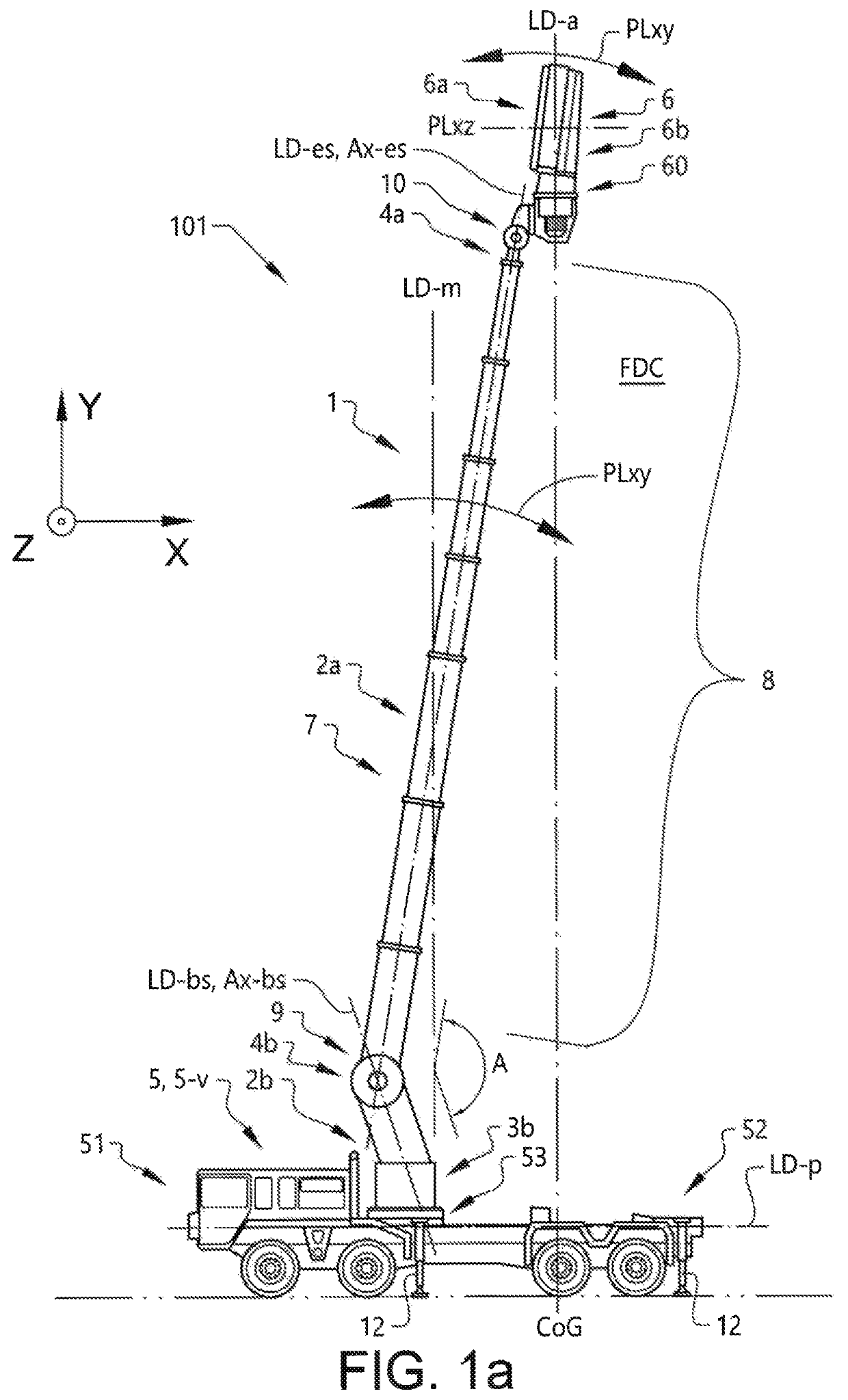
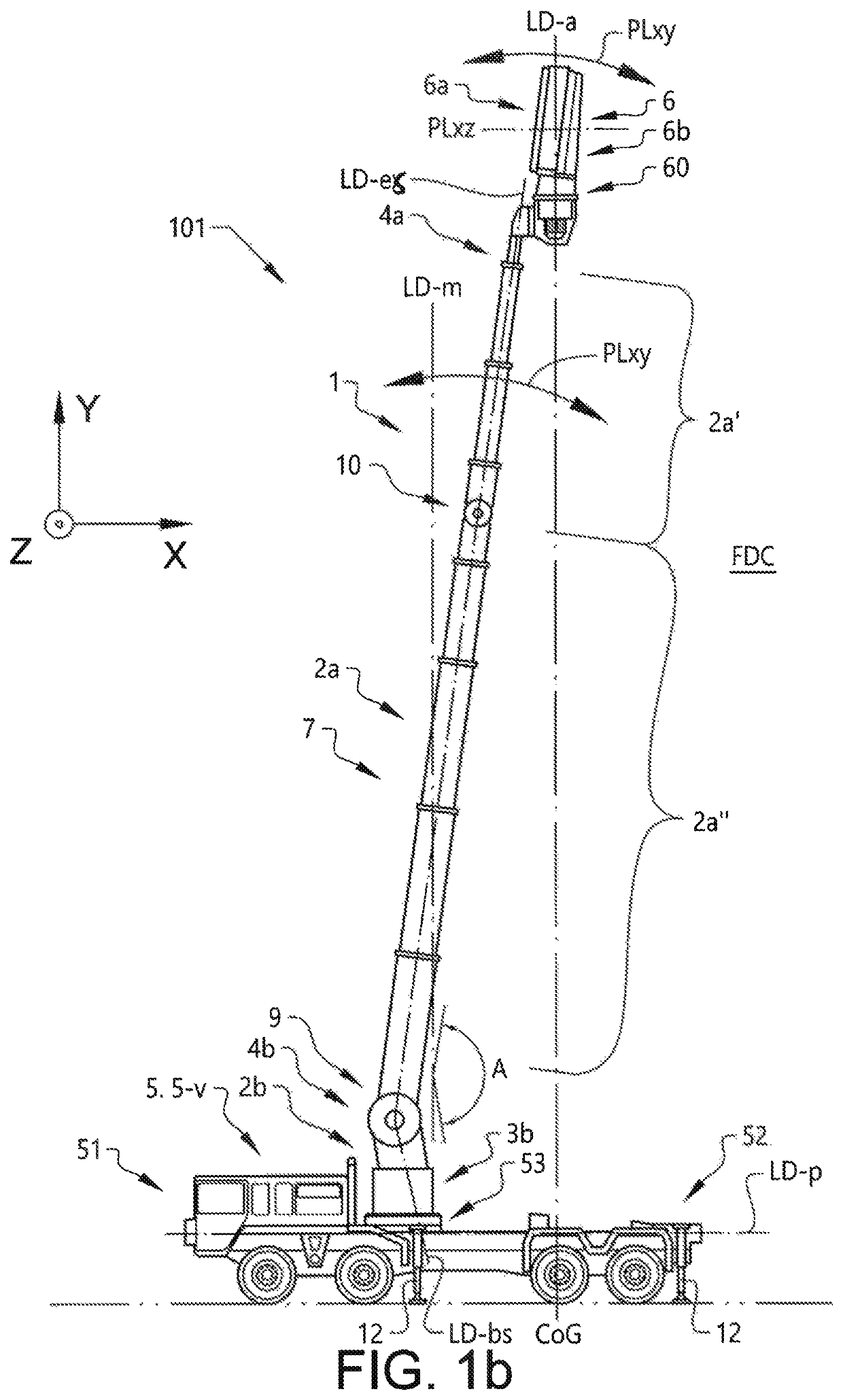
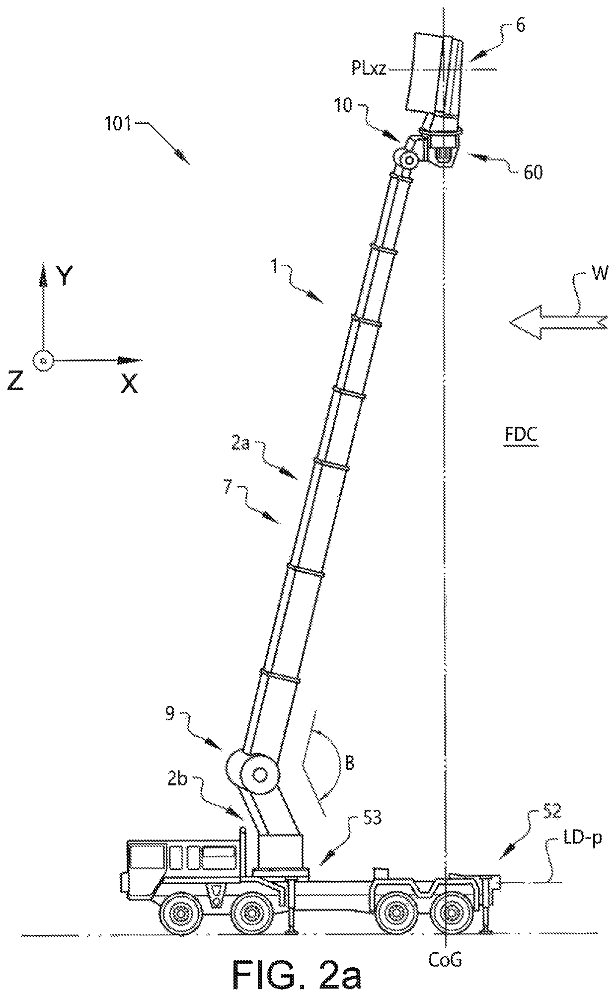
The disclosure relates to an antenna system [1] comprising a mast [7], in turn comprising a base section [2b] and an extendable section [a], and an antenna [6]. The antenna [6] is arranged to be rotatable and the extendable section [2a] comprises a plurality of telescopic sections [8] whereby the extendable section [2a] may adopt a retracted configuration and a deployed configuration. The mast [7] is foldable in relation to a platform [5] in a vertical plane [PLxy] essentially parallel to the longitudinal direction of the extendable section [LD-es] and to the longitudinal direction of the base section [LD-bs] by means of a first pivot joint [9]. According to the disclosure the antenna system [1] may be arranged to the platform [5], wherein the platform [5] may be in form of a vehicle [5-v], whereby an antenna arrangement [101] is formed. The disclosure further relates to methods of avoiding oscillations for an antenna system [1] and/or an antenna arrangement [101], and to a method of undeploying an antenna arrangement [101].

Description

CROSS REFERENCE TO RELATED APPLICATIONS[0001]This application is a National Stage Application, filed under 35 U.S.C. 371, of International Application No. PCT / SE2018 / 050007, filed Dec. 28, 2017; the contents of which is hereby incorporated by reference in its entirety.BACKGROUNDRelated Field[0002]The disclosure relates to an improved, more flexible, antenna system, an antenna arrangement and methods related thereto. The disclosed antenna system can be arranged to a vehicle, such as e.g. a terrain vehicle.Description of Related Art[0003]The performance in terms of reach and accuracy of antenna systems is determined by a number of factors whereof elevation, i.e. the height the antenna can be elevated to, of the antenna is one of the most influential. Mobile antenna systems, i.e. radar antennas or similar arranged to vehicles, have operational advantages since they offer improved flexibility since they fairly easy can be relocated. Antenna systems of mobile applications generally consi...

Claims


Application Information

Patent Timeline
IPC IPC(8): H01Q1/12H01Q1/18H01Q1/00
CPCH01Q1/185H01Q1/005H01Q1/1235H01Q1/12H01Q1/1264H01Q1/3216
Inventor RYDEN, JAN
Owner SAAB AB
Why Eureka
Try Eureka