Plant-growing tray

a plant tray and growing tray technology, applied in the field of plant tray, can solve the problems of occupying a large space, prone to tipping, and occupying a lot of space, and inserted into the cells in a repeatable, central position in the cell, and avoiding the effect of a repeatable central position

Active Publication Date: 2022-10-25
INT PLANT PROPAGATION TECH LTD
View PDF12 Cites 0 Cited by
  • Summary
  • Abstract
  • Description
  • Claims
  • Application Information

AI Technical Summary

Benefits of technology

[0016]By providing a support member which is configured to support an upper portion of the stabilised medium, the present invention may advantageously provide a nesting tray which is capable of supporting a stabilised medium in a predetermined upright position in the tray.
[0087]Preferably the tray is formed from injection-moulded plastic. Injection-moulded plastic may advantageously provide a tray that is stronger, and more rigid, than thermoformed plastic trays. This may allow injection-mouded trays to support the weight of the tray when the cells are loaded with compost, plants and water.

Problems solved by technology

Well-developed rootballs can be removed from cells all together as a single unit of compost and plant roots, but this only works when enough roots have developed to hold the compost together.
However, this is not possible with loose-filled compost, which is a problem in the industry.
While such trays are effective, they require a lot of (typically plastic) material, and the vertical ribs and cell walls also prevent the trays from “nesting” (sitting one inside another) in one another for storage and transport.
These trays are thus designed to stand, or stack, one on top of another, and they occupy a lot of space during storage and transport.
While the bottom of the tapered cells may hold the base of the stabilised media in position, these tapered cells have the problem that stabilised media, in particular cylindrical stabilised media, inserted into the cells are prone to tip over rather than standing upright in a repeatable, central position in the cell.
This is problematic for a number of automated processes involved in plant propagation, as the stabilised media are not positioned uniformly within the cells of the tray.
This is also undesirable for the growth of the plant in the stabilised medium, as the plant may grow out of the stabilised medium at an angle, and the airflow round the stabilised medium may be uneven.

Method used


Image

  • Plant-growing tray
  • Plant-growing tray
  • Plant-growing tray

Examples


first embodiment

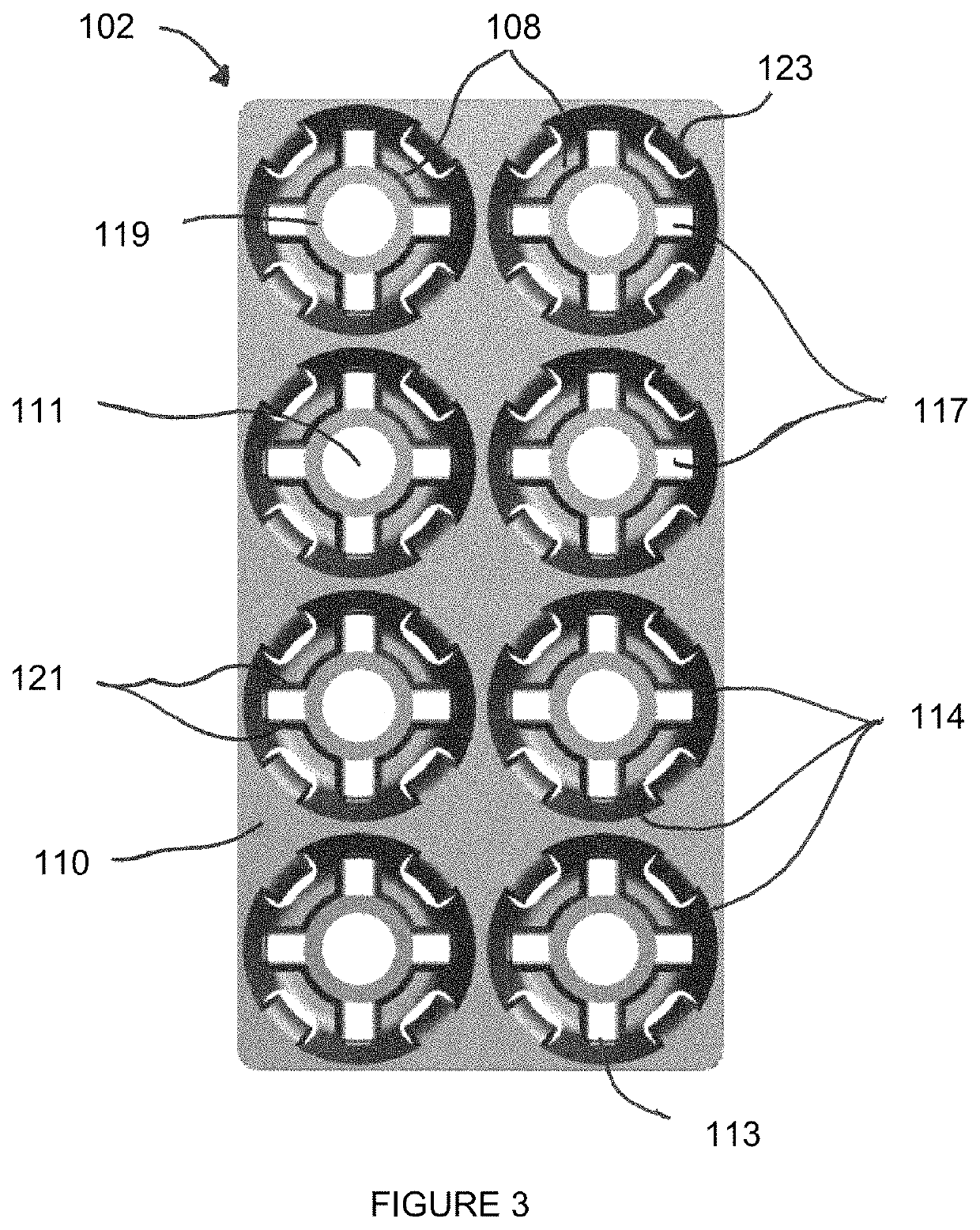
[0100]FIG. 3 is a plan view of a plant tray according to the invention;

[0101]FIG. 4 is a perspective view, from above, of the tray of FIG. 3;

[0102]FIG. 5 is a perspective view of the underside of the plant tray in FIGS. 3 and 4;

second embodiment

[0103]FIG. 6 is a plan view of a plant tray according to the invention;

[0104]FIG. 7 is an enlarged partial plan view of a portion of the plant tray of FIG. 6;

[0105]FIG. 8 is a perspective view, from above, of the portion of the plant tray shown in FIG. 7;

[0106]FIG. 9 is an enlarged partial plan view of the portion of the plant tray shown in FIGS. 7 and 8, containing a stabilised medium;

[0107]FIG. 10 is a perspective view, from above, of the portion of the plant tray shown in FIGS. 7 to 9, containing a stabilised medium;

[0108]FIG. 11 is a vertical cross-section of the portion of the plant tray shown in FIGS. 9 and 10 taken along the line A-A;

[0109]FIG. 12 is a vertical cross-section of the portion of the plant tray shown in FIGS. 9 and 10 taken along the line B-B;

[0110]FIGS. 13A, 13B and 13C illustrate a nestable upper projection according to a preferred embodiment of the present invention.

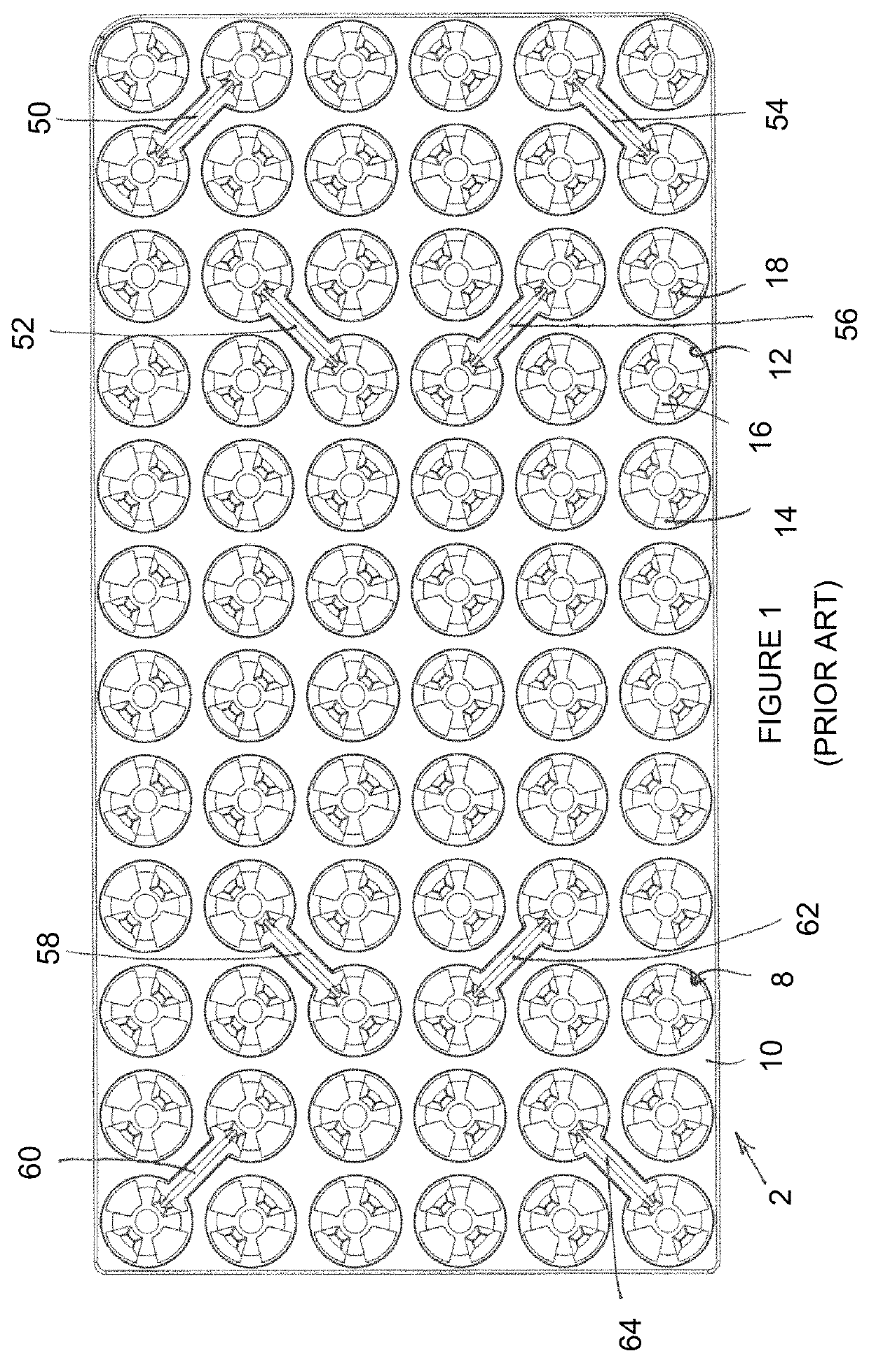
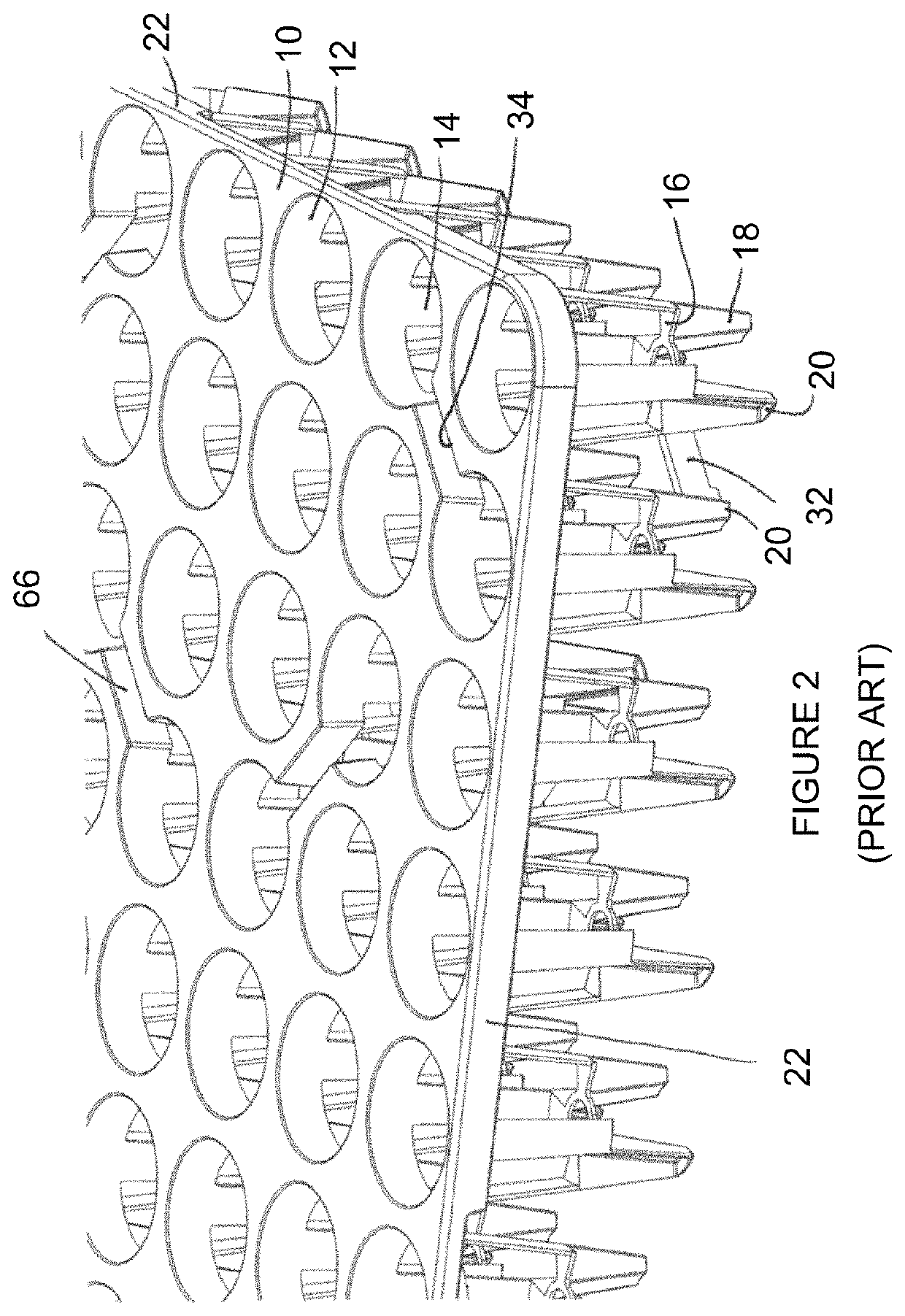
[0111]FIGS. 1 and 2 illustrate a prior art plant tray 2, as described in WO2010 / 103276. The pri...


PUM


Abstract

A plant-growing tray (102) comprises an array of cells (108) for containing stabilised media for propagating plants. The tray comprises a tray top (110), and each cell comprises a base (116) and an inclined side wall (114) extending from the base to the tray top. Each cell is configured to receive a stabilised medium, and comprises a plurality of projections (123), positioned around the side wall and facing into the cell, and a plurality of openings (125) defined in the side wall below the projections. The projections (123) are configured in use to support an upper portion of the stabilised medium. In a further aspect, a plant-growing tray for containing stabilised media for propagating plants is configurable in a nesting configuration with a similar tray, and comprises: a tray base configured to support a base portion of a stabilised medium; a support member, configured to support an upper portion of the stabilised medium; and an inclined tray wall connecting the support member to the tray base.

Description

[0001]The invention relates to a plant-growing tray, or frame, and in particular to a plant-growing tray for containing stabilised media for propagating plants.BACKGROUND[0002]In commercial plant-propagation systems, plants may be grown, or propagated, with their roots in any of a number of conventional growing media, such as soil, peat or coir. For convenience in this document growing media of all kinds will be referred to by the generic term “compost”.[0003]When large numbers of plants are to be propagated, they may be arranged in trays, each tray being capable of holding a plurality of plants, such as typically between 20 and 800 plants. In some cases, the trays are handled by hand and in some cases they are handled by automated machinery. In use, the trays are typically arranged on the ground or on benching or tables.[0004]Plant trays of this type are sometimes termed plant frames. The word tray will be used to include both terms in this document.[0005]A tray typically comprises...

Claims


Application Information

Patent Timeline
Patent Type & Authority Patents(United States)
IPC IPC(8): A01G9/02
CPCA01G9/027A01G9/021A01G9/0295
Inventor COOLEY, JOHN
Owner INT PLANT PROPAGATION TECH LTD
Why Eureka
Try Eureka