Method and machine for changing agricultural mulch

a technology for agricultural mulch and machines, applied in the field of agricultural mulch change machines, can solve the problems of difficult removal of used film, high labor intensity, and high cost of disposal of used film, and achieve the effects of saving time, effort, and expense, and extending the useful life of partially degraded film

Inactive Publication Date: 2001-08-02
CLARKE PAUL W W +1
View PDF0 Cites 10 Cited by
  • Summary
  • Abstract
  • Description
  • Claims
  • Application Information

AI Technical Summary

Benefits of technology

[0013] Accordingly, the invention addresses and overcomes the problems posed by the prior art The invention provides an effective, convenient, and economical method of changing the exposed surface of mulch. Specifically, the invention has several objects and advantages.
[0021] Eighth, the invention provides the ability to be drawn behind a standard mulch laying machine. This provides the advantage of allowing initial application of a second layer, which is desirable where the farmer wishes to expose the bottom layer by later removing the second layer.

Problems solved by technology

Removal of used film may be difficult, requiring extensive manual labor.
Disposal of used film can also be costly due to traces of pesticides and fertilizer applied to the crops.
Mulch selection is a compromise between the requirements of the two crops, or costly replacement must be performed during the middle of the season.
Prior art has not adequately addressed the need to change plastic film mulch color and light absorption characteristics.
The problems with removal and replacement are that it results in an expense for removal and disposal, damages the plastic mulch so it cannot be reused, and potentially damages the crop itself.
Because of the many variables affecting degradation of the top layer and exposure of the bottom layer such as weather and durability of the top layer, proper control of the process has not been achieved.
The farmer cannot control when the bottom layer will be exposed and the land is also littered with remnants of the deteriorated top layer.
The problem with this method, however, is that the key element of reflective plastic is its metalized surface, and such metalization cannot be done in the field.
Therefore, this method also does not adequately address the problem of how to change the exposed surface of mulch.

Method used


Image

  • Method and machine for changing agricultural mulch
  • Method and machine for changing agricultural mulch
  • Method and machine for changing agricultural mulch

Examples


Embodiment Construction

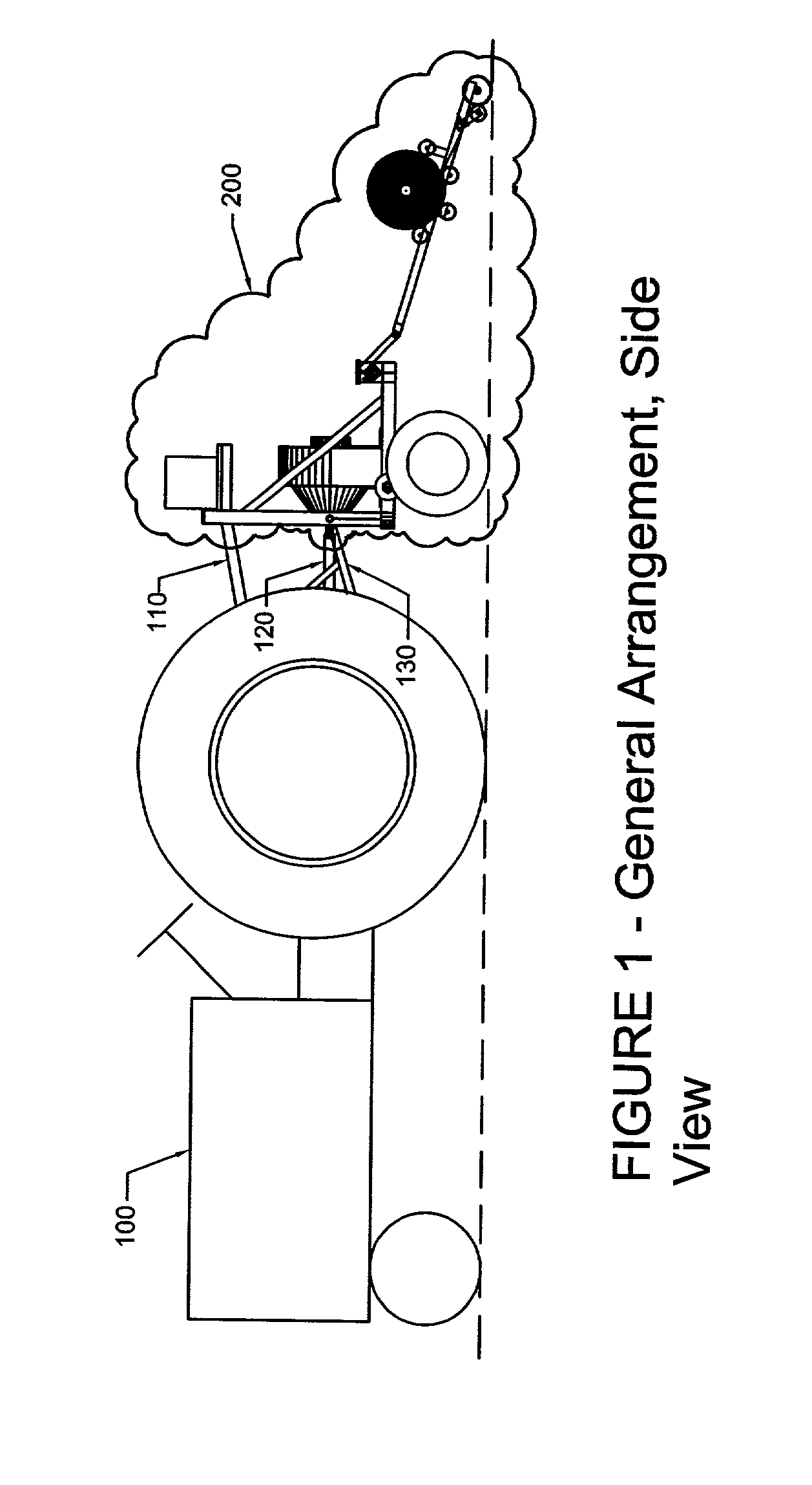
[0066] FIG. 1 illustrates the Field Plastic Laminating Machine 200 attached to a farm tractor 100 using the 3-point hitch top arm 110 and the 3-point hitch bottom arms 130. The blower drive (either tractor hydraulic or tractor power take-off) is connected to the tractor FIG. 1 illustrates the connection of a power take-off universal shaft 120 to the pressure blower input shaft 225.

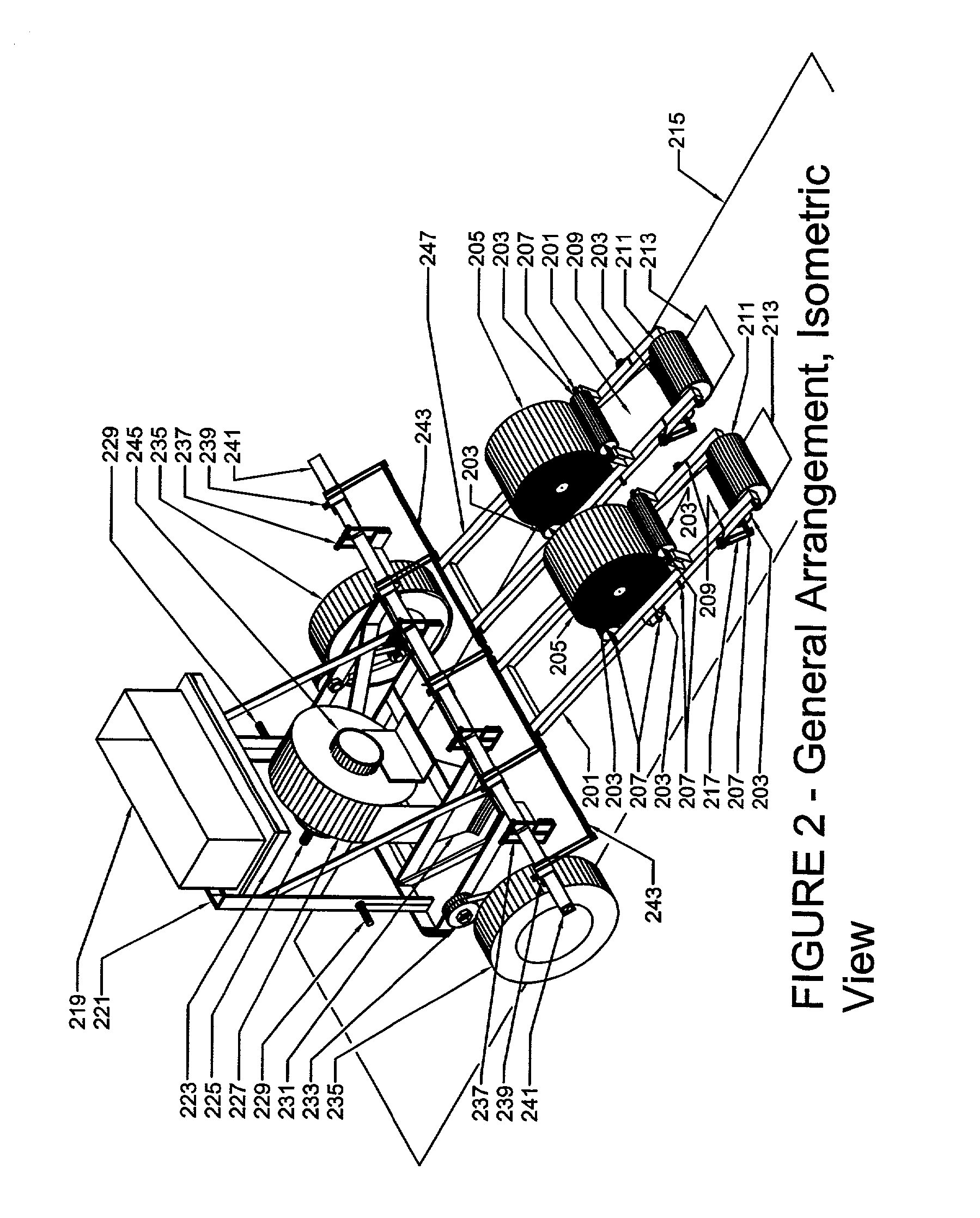
[0067] The significant machine components illustrated in FIG. 2 are the carrier frame 221 which is an industry standard welded fabrication of hot rolled structural steel shapes and forged steel hitch pins 229 with rubber tire, rim and axle 235 mounted on an adjustable height wheel mount 233; the toolbar 241 that is attached to the carrier frame by mounts 237; the carrier swivel rod 243 attached to the toolbar 241 by adjustable toolbar clamps 239, the pressure blower 227, attached pressure blower outlet nozzle 231 and attached pressure blower inlet 245. and the film roll stock carrier frame attached to the ...


PUM


Abstract

A method and machine for changing or renewing the color and / or light reflection, transmission, and absorption characteristics of an existing layer of synthetic agricultural mulch or prolonging the usefulness of said existing mulch by applying a layer of new mulch to the preexisting mulch in a cultivated field using heat welding / fusion or adhesive or mechanical fastening for attachment of new mulch to existing mulch and at least one blower for clearing debris from the existing mulch prior to application of new mulch, with the machine being able to be drawn by a tractor, laborer, or draft animal.

Description

CROSS-REFERENCE TO RELATED PATENT APPLICATION[0001] This application claims the benefit of patent application Ser. No. 09 / 353,093 which claims benefit of provisional patent application No. 60 / 092,810, the disclosure of which is incorporated herein by reference as though recited in full.[0002] This invention relates to agricultural mulch, specifically to a method and machine for changing or renewing the exposed surface of synthetic agricultural mulch in order to enhance agricultural quality and yield.BRIEF DESCRIPTION OF THE PRIOR ART[0003] Agricultural plastic film mulch is a layer of plastic film placed on the soil near or surrounding seeds or crops to enhance growth and yield. Farmers have long used a variety of mulches including straw and wood chips, biodegradable paper, and plastic film. Mulches in general can reduce weed growth by restricting light and oxygen, and protect seeds from foraging animals. Plastic film mulch is in widespread use in the truck farming and nursery indus...

Claims


Application Information

Patent Timeline
Patent Type & Authority Applications(United States)
IPC IPC(8): A01G13/02
CPCA01G13/0287
Inventor CLARKE, PAUL W.W.SCRUBY, TIMOTHY M.
Owner CLARKE PAUL W W
Why Eureka
Try Eureka