Heat energy recycling device for producing biogas by waste heat and operating mode thereof

An operation mode, biogas technology, applied in biological sludge treatment, waste fuel and other directions, can solve the problems of consuming large heat energy, polluting the environment, aggravating the greenhouse effect, etc., to reduce operating costs, save heat energy, and improve economic benefits.

Inactive Publication Date: 2013-09-18
哈尔滨瀚科环境工程设计研究院有限公司
View PDF5 Cites 9 Cited by
  • Summary
  • Abstract
  • Description
  • Claims
  • Application Information

AI Technical Summary

Problems solved by technology

However, in the severe cold regions of the north, the temperature in winter is very low, reaching minus 20-30°C, and the temperature of livestock manure (biogas raw material) in livestock farms is generally 2°C, and these manure must be heated to 35°C to enter the anaerobic fermentation tank for fermentation and decomposition Biogas production is currently heated by hot water (or steam) produced by hot water boilers (or steam boilers), which consumes a lot of heat energy, thereby reducing the economic benefits of biogas plants; The temperature of biogas residue and biogas slurry is 35°C. In the past, it was directly discharged into the natural environment for cooling, which aggravated the greenhouse effect and polluted the environment.

Method used


Image

  • Heat energy recycling device for producing biogas by waste heat and operating mode thereof

Examples


Embodiment 1

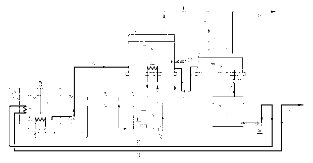
[0030] Such as figure 1 As shown, a thermal energy recycling device for producing biogas by using waste heat and its operation mode are characterized in that the device is composed of a raw material blending pool 1, a raw material blending pool mixer 2, a raw material pump 3, a primary raw material heater 4, and a secondary raw material Heater 5, anaerobic fermentation tank 6, anaerobic tank heater 7, secondary fermentation tank and gas storage tank 8, biogas residue biogas slurry pool 9, biogas residue biogas slurry delivery pump 10, hot water boiler 11, hot water circulation Pump 12, raw material delivery pipeline 13 from raw material blending tank to anaerobic fermentation tank, hot water supply pipeline 14, hot water return pipeline 15, biogas residue transported from anaerobic fermentation tank to secondary fermentation tank and gas storage tank The biogas slurry delivery pipeline 16, the pipeline 17 for introducing the biogas produced by the anaerobic fermentation tank i...

Embodiment 2

[0032] Such as figure 1 As shown, the positional relationship of each component of a thermal energy recycling device that utilizes waste heat to produce biogas is as follows: the raw material inlet 23 is on the upper part of the raw material blending pool 1, and is used to send raw materials into the raw material blending pool 1; the primary raw material heater 4 , installed on the wall of the raw material blending pool 1 in a suspended manner, is a high-temperature biogas residue and biogas slurry heater; the secondary raw material heater 5, in the raw material blending pool 1, is a hot water heater; the raw material blending pool mixer 2, in The raw material blending pool 1 plays the role of blending and stirring.

[0033] The high-temperature biogas residue biogas slurry delivery pipeline 20 is a delivery pipeline connecting the biogas residue biogas slurry tank 9 and the primary raw material heater 4, and transports the 35°C high-temperature biogas residue biogas slurry fr...

Embodiment 3

[0039] Such as figure 1 As shown, the operation mode of a thermal energy recycling device that utilizes waste heat to produce biogas is as follows:

[0040] (1) Open the discharge valve 22 of the secondary fermentation tank, and discharge the biogas residue and biogas slurry at a high temperature of 35°C in the secondary fermentation tank and the gas storage tank 8 to the biogas residue and biogas slurry tank 9 . When the liquid level of the secondary fermentation tank and the gas holder 8 reaches a suitable low level, close the discharge valve 22 of the secondary fermentation tank and stop discharging.

[0041] (2) Open the discharge valve 26 of the anaerobic fermentation tank, and discharge the biogas residue and biogas slurry at a high temperature of 35°C to the secondary fermentation tank and the gas storage tank 8, so that the liquid level of the secondary fermentation tank and the gas storage tank 8 reaches a high level, Close the anaerobic fermenter drain valve 26. At...


PUM


Abstract

The invention belongs to the technical field of environmental protection and energy conservation, and in particular relates to a heat energy recycling device for producing biogas by waste heat and an operating mode thereof. In northern cold areas, temperature in winter is very low and reaches -20 to 30 DEG C, and temperature of excrement of animals (biogas raw material) in a livestock farm is ordinarily 2 DEG C. The excrement which has to be heated to 35 DEG C enters into an anaerobic fermentation tank to ferment and decompose to produce biogas. In present, hot water (or steam) generated by a hot water boiler (or a steam boiler) is adopted to heat, and a lot of heat energy is consumed. According to the invention, temperature difference between high temperature biogas residue and biogas liquid discharged by a biogas plant and the raw material (excrement of animals) exists to transfer heat, so that high temperature biogas residue and biogas liquid after anaerobic fermentation are used as a primary heating source to heat low temperature raw material. Heat required by heating the raw material can be reduced by about 45% to realize the energy-saving purpose, and the economic benefit of the biogas plant is improved.

Description

[0001] technical field [0002] The patent of the present invention belongs to the technical field of environmental protection and energy saving, and specifically relates to a thermal energy recycling device and its operation mode for producing biogas by utilizing waste heat of biogas residue and biogas liquid. Background technique [0003] In order to protect the environment and make full use of energy, large-scale livestock farms (pig farms, cattle farms, chicken farms, etc.) have built biogas plants, which use livestock manure and sewage as raw materials to produce biogas through anaerobic fermentation. Biogas is used as fuel or power generation, and the generated biogas residue can be used as high-quality organic fertilizer. However, in the severe cold regions of the north, the temperature in winter is very low, reaching minus 20-30°C, and the temperature of livestock manure (biogas raw material) in livestock farms is generally 2°C, and these manure must be heated to 35°...

Claims


Application Information

Patent Timeline
Patent Type & Authority Applications(China)
IPC IPC(8): C02F11/04
CPCY02E50/30
Inventor 于志滨梁玉文曹毅王明伟
Owner 哈尔滨瀚科环境工程设计研究院有限公司
Why Eureka
Try Eureka