
Interface element used on a snowboard

a technology of interface elements and snowboards, applied in the direction of skis, skates, sports apparatus, etc., can solve the problems of inability to effectively transmit thrust, inaccuracy in feel and therefore in control of the board, and material that does not allow the user to transmit loads at the front and/or rear ends of the foot,

Inactive Publication Date: 2001-08-23
SKIS ROSSIGNOL
View PDF0 Cites 36 Cited by
  • Summary
  • Abstract
  • Description
  • Claims
  • Application Information

AI Technical Summary

Benefits of technology

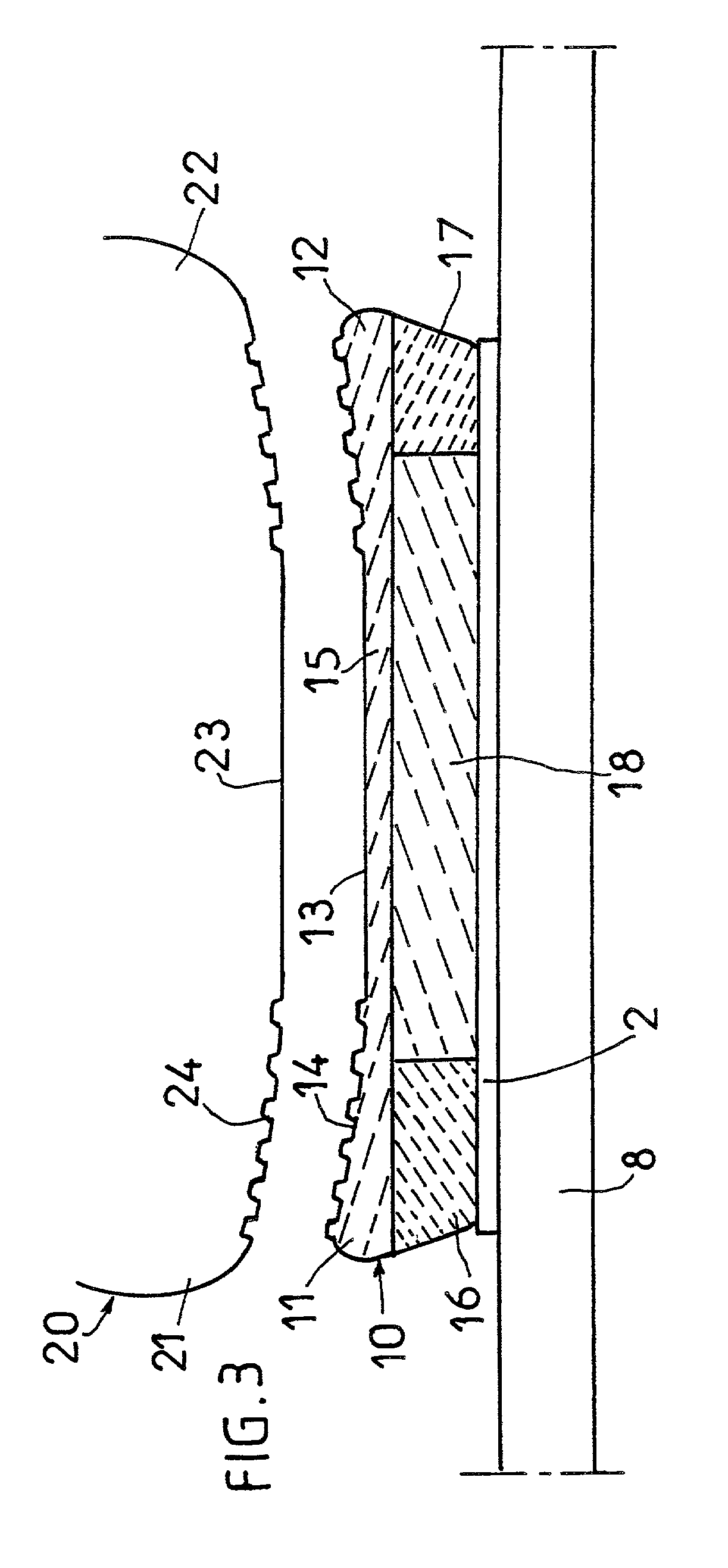
[0020] In other words, the characteristic element is made of a material which can adopt the exact shape of the underside of the sole of the boot, which allows the boot to be immobilized extremely precisely in position with respect to the binding.
[0021] The collaboration between the patterns on the sole and the corresponding patterns molded in the thermoformable zone provides almost perfect immobilization of the boot with respect to the binding, regardless of the sole geometry.
[0022] Furthermore, the thermoformable material used is compressed and therefore rigidified at the time of molding by the sole, which increases its ability to transmit thrust, particularly by comparison with the devices of the prior art made of elastomeric materials.
[0026] In an advantageous form, the interface element comprises, at the front and / or rear ends, and beneath the zone of thermoformable material, an additional zone of rigid material so as to provide for good transmission of thrust exerted toward the board.
[0028] When the interface element extends under the entire length of the boot, it may prove advantageous for it to comprise at least in the region of the heel and beneath or at the location of the zone of deformable material, a zone of flexible material so as to damp vibrations from the board, and to damp jolts, particularly when taking jumps.
[0030] Advantageously in practice, the interface element according to the invention may be covered with an impervious protective layer made, for example, of a fabric coated with polytetrafluoroethylene. Such a protective layer prevents snow, water and ice from getting into the cells of the foam of the thermoformable element. Such a protective layer may also bear decoration.

Problems solved by technology

This volume which is free of material therefore does not allow the user to transmit loads at the front and / or rear ends of the foot, even though, as is known, these constitute one of the main zones for the transmission of thrust.
It is to be noted that this problem of effectively transmitting thrust arises to a greater extent at the front end of the boot because thrust at the rear end of the boot is transmitted mainly via the highback of the binding.
Nonetheless, the absence of effective support at the rear of the heel of the boot leads to inaccuracies in the feel and therefore in the control of the board.
The major drawback with these wedge-forming elements is that they are not able to adapt to suit different boot sizes, and that they therefore have to be repositioned each time the user changes boots.
However, as the element has a given shape, it cannot correspond to all shapes of boot soles on the market.
Such a solution therefore has the major drawback that the wedge-forming element is present on only part of the surface of the sole of the boot, which means that the bearing surface of the boot is not used to the full and that some of the loads exerted by the user is not put to good use.
This clearance produces the aforementioned detrimental effects.
Finally, a certain amount of slippage may arise between the top face of the wedge-forming element and the sole, thus limiting the effectiveness with which loads are transmitted.
Furthermore, the thermoformable material used is compressed and therefore rigidified at the time of molding by the sole, which increases its ability to transmit thrust, particularly by comparison with the devices of the prior art made of elastomeric materials.

Method used


Image

  • Interface element used on a snowboard
  • Interface element used on a snowboard
  • Interface element used on a snowboard

Examples


Embodiment Construction

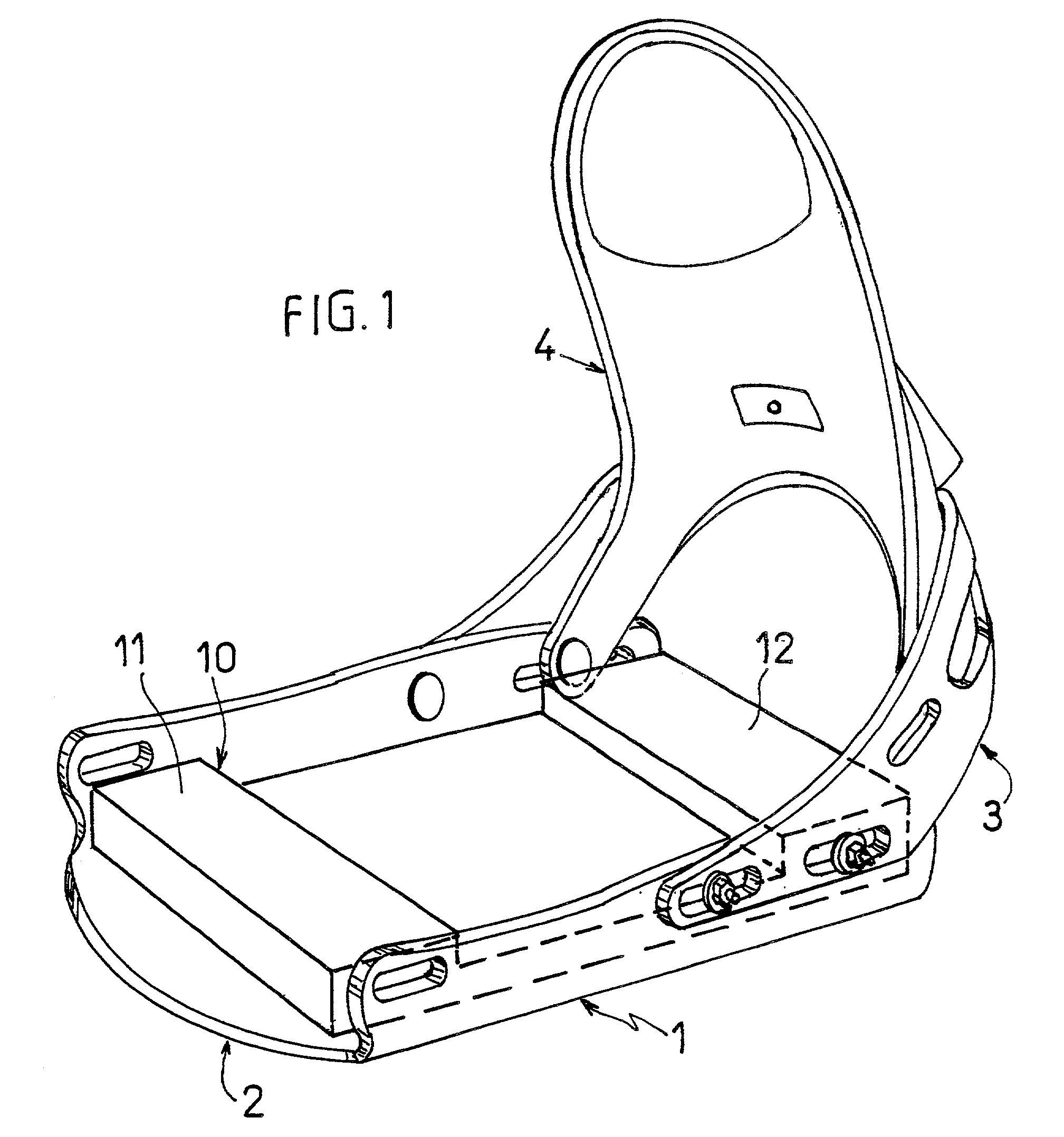
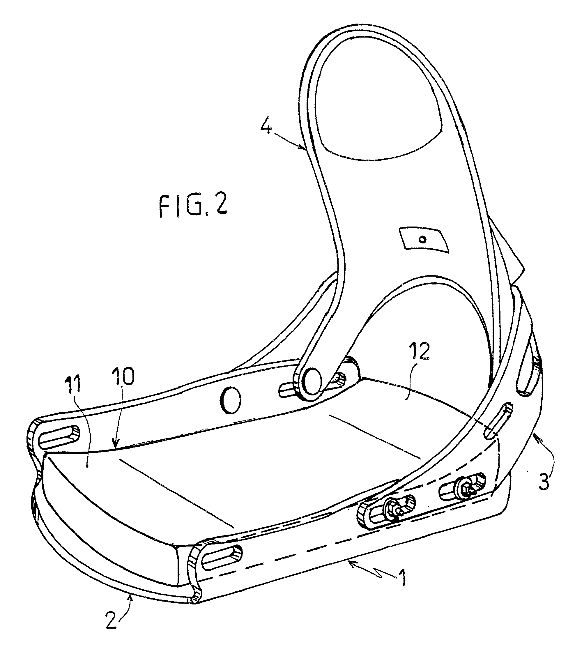
[0037] As already stated, the invention relates to an interface element intended to be fitted between the sole of the boot and the binding or the top side of the board, so as to compensate for the curvature of the sole of the boot.

[0038] As illustrated in FIG. 1, the characteristic element (10) can be fitted on the base (2) of the binding (1).

[0039] In the embodiment illustrated, this base (2) comprises a rear bow (3) passing behind the foot and holding an articulated highback (4) intended to act as rear support for the boot upper.

[0040] Obviously, the invention is not restricted to this single binding architecture and can be used in particular in so-called "baseless" bindings which have no actual base proper but just have two lateral members, the interface element then resting directly on the top side of the board (8).

[0041] In the same way, the invention is not restricted to the embodiment illustrated in FIG. 1 in which the interface element (10) extends over the entire surface of...


PUM


Abstract

An interface element (10) used on a gliding board, said element being inserted between the sole (20) of the user's boot and the top side of the board (8) so as to take the thrust exerted toward the board by the user at least at the front end of the sole, and which comprises at least one zone (11, 12, 15) made of a thermoformable material capable, after exposure to heat, of matching the imprint of at least the front end (21) of the sole (20) of the boot so as to fill the volume between the top side (8) of the board and the sole of the boot (20).

Description

[0001] The invention relates to the field of gliding sports and, more particularly, to that of snowboarding. It relates more specifically to an interface element fitted between the sole of the boot and the binding (or the snowboard) to fill the gap between the sole and the binding or the board. Such interface elements are commonly known in snowboarding by the name of "gas pedal".[0002] In the remainder of the description, the invention is described in its application to snowboarding, but it could be carried over to any kind of gliding board such as for alpine skiing, cross-country skiing or the like.PRIOR ART[0003] As is known, snowboarding is done either with rigid boots that resemble alpine ski boots or with flexible boots that collaborate with bindings that have rigid elements, particularly a highback, intended to provide support for the flexible boot.[0004] The invention relates more precisely to this family of flexible boots and appropriate bindings.[0005] Such boots are actual...

Claims


Application Information

Patent Timeline
IPC IPC(8): A63C10/22A63C10/24A63C10/28
CPCA63C10/22A63C10/24A63C10/285
Inventor JOUBERT DES OUCHES, PASCAL
Owner SKIS ROSSIGNOL
Learn More