Device for aircraft thrust recovery capable of linking a turboshaft engine and an engine strut

Inactive Publication Date: 2001-10-04
EADS AIRBUS
View PDF0 Cites 37 Cited by
  • Summary
  • Abstract
  • Description
  • Claims
  • Application Information

AI Technical Summary

Problems solved by technology

However, it has the inconvenience of having to transit the thrust force along the same pivoting axes both in normal operational conditions and in the case of rupture of one of the parts.
This thrust recovery device has the main inconvenience of becoming non-operational when

Method used


Image

  • Device for aircraft thrust recovery capable of linking a turboshaft engine and an engine strut
  • Device for aircraft thrust recovery capable of linking a turboshaft engine and an engine strut

Examples


Embodiment Construction

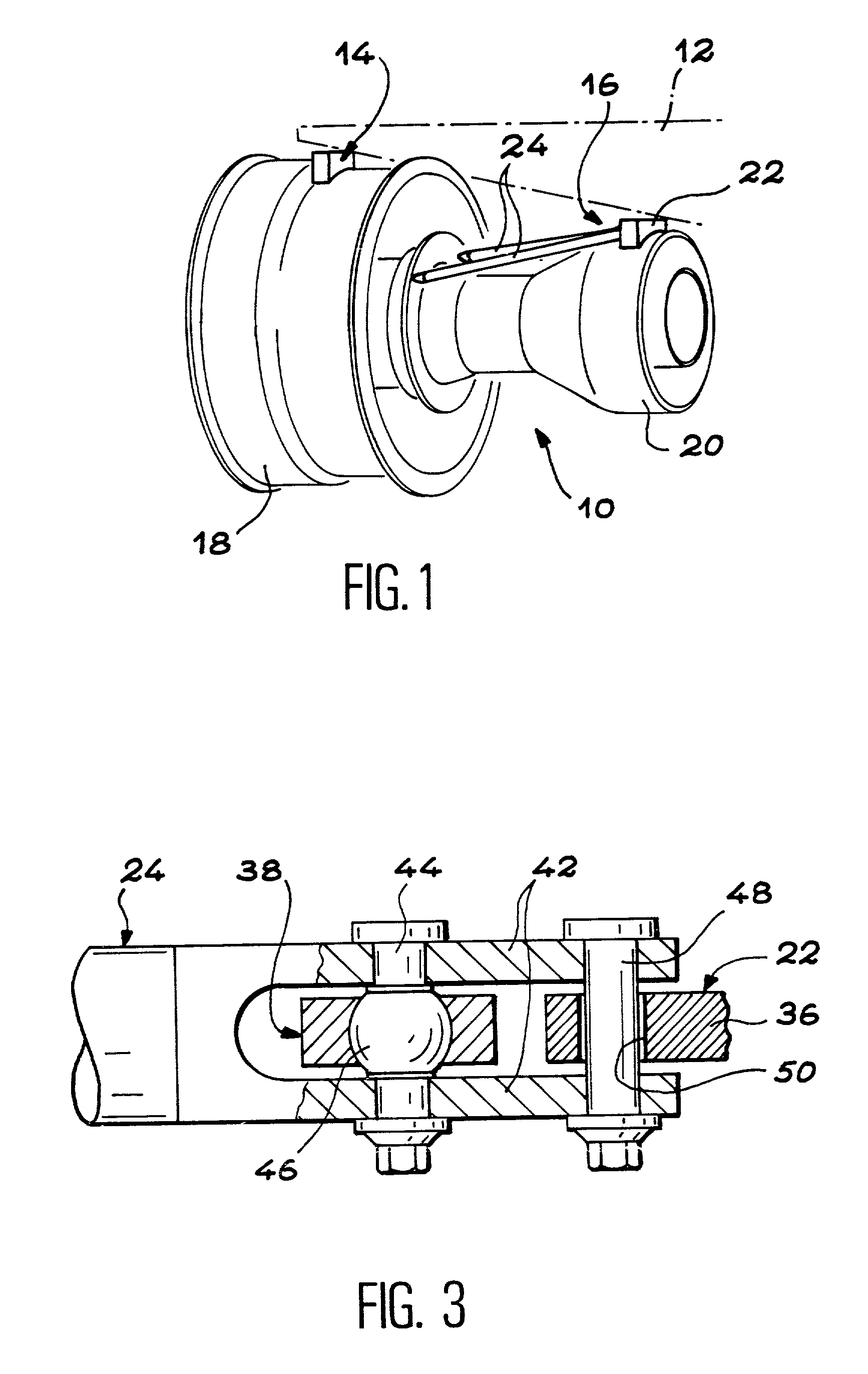
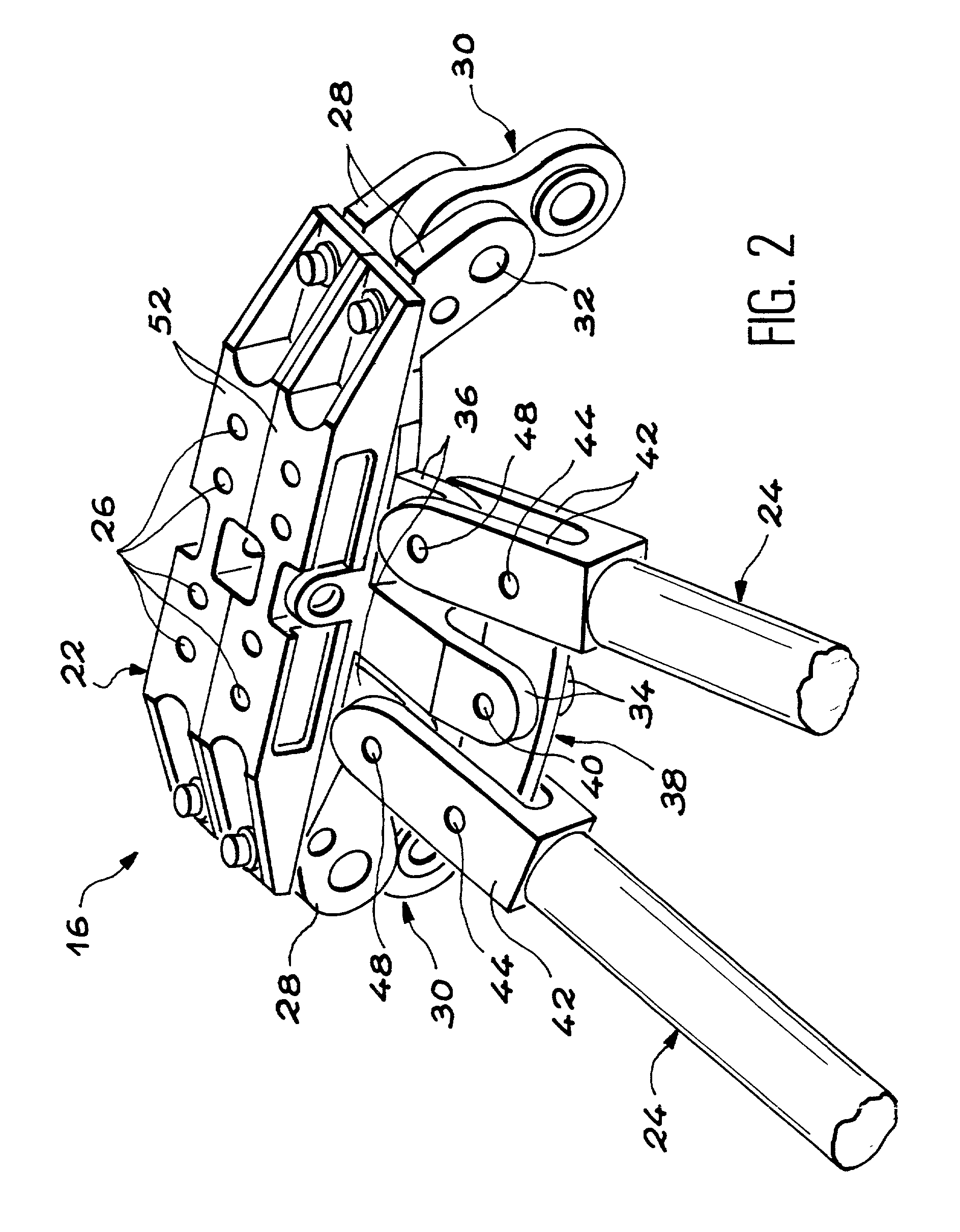
[0012] The objective of the invention is a device for thrust recovery designed to ensure the link between a turboshaft engine and an engine strut of an aircraft, this device being fitted in such a way that it has reduced mass and dimensions and ensures the transmission of the thrust force even in the event of rupture of any one of the parts constituting it.

[0013] According to the invention this result is obtained by means of a thrust recovery device, capable of linking a turboshaft engine and an engine strut of an aircraft, the device comprising:

[0014] an attachment fitting able to be fixed to the engine strut, said attachment fitting comprising a central yoke and two lateral yokes;

[0015] a control bar containing a central part articulated on the central yoke of the attachment fitting by a first pivoting axis; and

[0016] two coupling rods oriented almost along the direction of the turboshaft engine thrust and each comprising a front end able to be articulated on the turboshaft engine...


PUM


Abstract

Device for aircraft thrust recovery capable of linking a turboshaft engine and an engine strut. A device for thrust recovery (16) linking a turboshaft engine to an aircraft engine strut comprising an attachment fitting (22) fixed to an engine strut, a control bar (38) articulated on the attachment fittings (22) and two coupling rods (24) linking the control bar (38) to the central engine casing, almost along the longitudinal axis of the latter. Links with play are envisaged between each of the coupling rods (24) and the attachment fitting (22), to ensure transmission of thrust forces in the event of rupture of one of the parts of the device. These links with play comprise pivoting axes (48) which intersect the longitudinal axes of the corresponding coupling rods (24).

Description

[0001] The present invention relates to a device for thrust recovery, conceived for linking a turboshaft engine and an aircraft engine strut, so as to ensure transmission of the thrust forces of the turboshaft engine to the structure of the aircraft.[0002] In the text as a whole, the terms "front" and "rear" refer to the direction of the airflow in the turboshaft engine, from the front to the rear.PRIOR ART[0003] Turboshaft engines ensuring propulsion of aircraft are usually mounted under the wings or inside the tail unit, through the intermediary of an engine strut. The link between the engine and the strut is ensured by two or three linkage devices designed to transmit to the aircraft structure, through the engine strut, the thrust of the engine. These thrusts comprise vertical loads such as the weight of the engine, axial loads resulting from the thrust produced by the engine, lateral loads due in particular to turbulence produced by the wind, and roll loads or torques resulting ...

Claims


Application Information

Patent Timeline
IPC IPC(8): B64D27/18B64D27/26
CPCB64D27/18B64D27/26B64D2027/266B64D2027/268
Inventor JULE, PASCALLEVERT, STEPHANE
Owner EADS AIRBUS
Why Eureka
Try Eureka