Method of providing electrical energy to devices without using prongs

a technology of electrical energy and prongs, applied in the direction of coupling device connections, coupling contact members, electric discharge lamps, etc., can solve the problems of limited capabilities and limited lives

Inactive Publication Date: 2001-11-29
PACUSMA
View PDF0 Cites 21 Cited by
  • Summary
  • Abstract
  • Description
  • Claims
  • Application Information

AI Technical Summary

Benefits of technology

[0013] According to a preferred embodiment, thin copper contacts are housed between two thin plastic pieces for secureness. Preferable thermoplastic materials include ABS and PBT. In applications that require a high electrical index rating for good insulation material as required by Underwriters Laboratory, for example, contacts can be housed within PBT, a relatively expensive material. Components that use PBT and other expensive materials preferably are provided in a modular form to minimize costs. The remainder of the wall plate can be made from standard electrical plastic such as ABS. Advantageously, the modular approach also provides a rapid and flexible way to develop new product lines. The module containing the contacts can be mounted on other devices or other wall plate housings designed to provide new product offerings. This approach can speed up the UL safety standard investigation cycle as new products are being developed by eliminating, for example, mechanical tests related to the contact components.

Problems solved by technology

On other devices, either a battery or a photoluminescent material is utilized, both of which have limited lives and limited capabilities.

Method used


Image

  • Method of providing electrical energy to devices without using prongs
  • Method of providing electrical energy to devices without using prongs
  • Method of providing electrical energy to devices without using prongs

Examples


Embodiment Construction

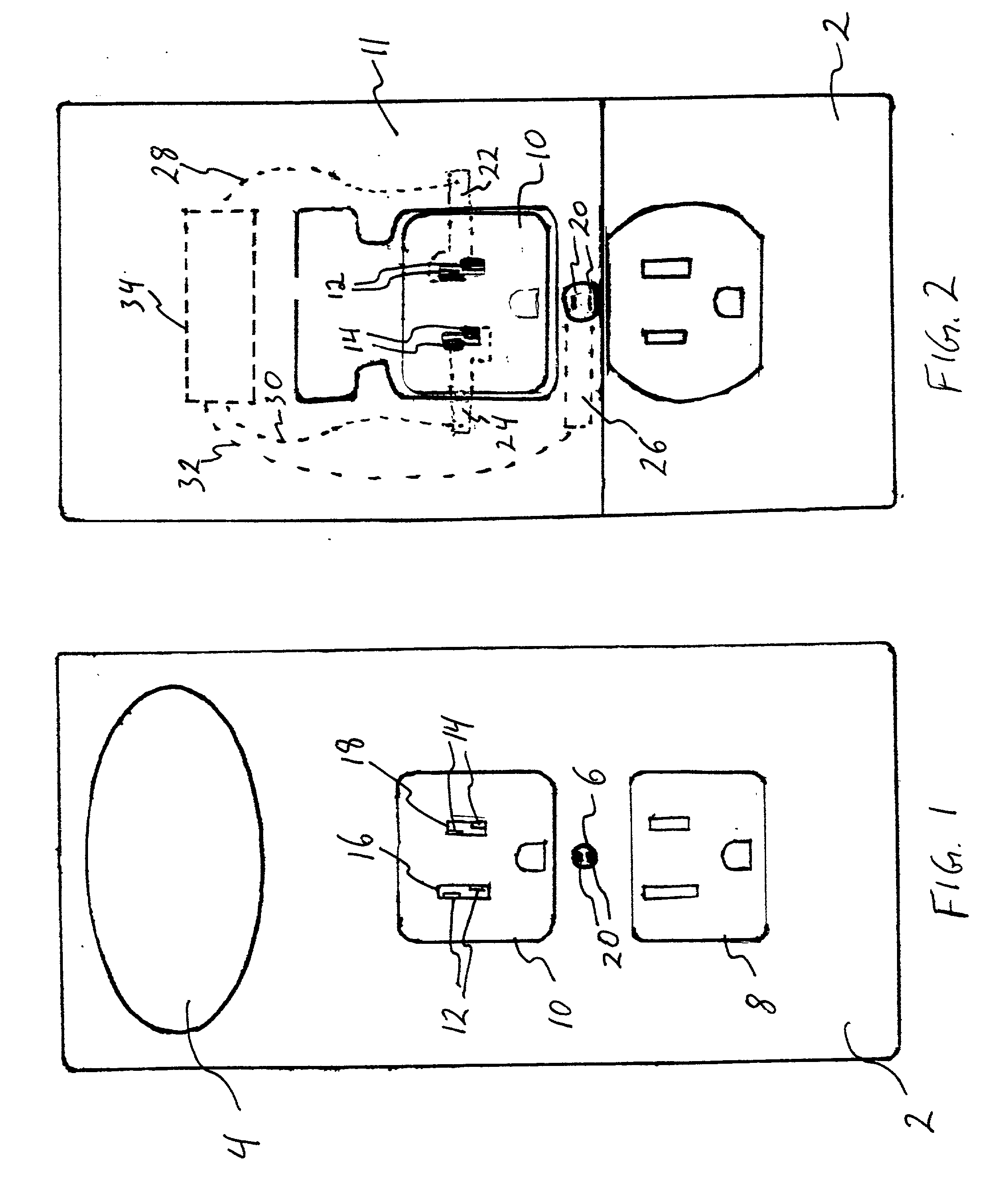
[0029] Referring initially to FIG. 1, a wall plate cover 2 according to the present invention is shown schematically in plan view. An flat panel night light 4 is mounted on the wall plate cover. The flat panel light is made from an electroluminescent material. The wall plate cover mounts over an existing duplex wall plate. Alternatively, the wall plate cover can be used to replace the existing wall plate. The wall plate cover 2 is secured in place using a wall plate screw inserted through hole 6.

[0030] Provided on the wall plate cover 2 are two receptacle covers 8 and 10. As shown in FIG. 1, lower receptacle cover 8 is simply a blank cutout in the wall plate cover 2. Upper receptacle cover 10 is provided with contacts 12 and 14 mounted on either side of the prong openings 16 and 18. The contacts 12, 14 are connected electrically to the light 4. As explained further below, when the prongs of an electrical plug are inserted through the prong openings 16 and 18, the prongs touch contac...


PUM


Abstract

Methods and apparatus for providing electrical energy to an electrical circuit without using a pronged plug are disclosed. A power connector includes a substrate with openings for receiving prongs of an electrical plug. Contacts supported on the substrate extend into the openings. The contacts are connected to the electrical circuit. The substrate is placed over an electrical outlet receptacle. When the prongs of the electrical plug are inserted through the two openings of the power connector and into the outlet receptacle, the prongs touch each of the contacts, respectively, such that electrical power can be supplied to the electrical circuit connected to the pair of contacts. The power connector can be incorporated into a wall plate mounted over an electrical outlet, either in place of or directly over an existing wall plate. An electrical circuit is housed within the wall plate. Typical electrical circuit devices powered by the present invention include night lights, emergency lights, air fresheners, air purifiers, pest controls, alarms, smoke detectors, carbon monoxide detectors, amplifiers, antennae, motion sensors, home security modules, home automation modules, surge protectors, electronic filters, load indicators, and home-wiring based network connections for telephones or local area networks (LANS).

Description

[0001] This application claims the benefit of U.S. Provisional Application Ser. No. 60 / 182,925 filed Feb. 16, 2000, the entire contents of which are incorporated herein by reference.[0002] 1. Field of the Invention[0003] The present invention relates to providing electrical energy to devices. More specifically, the invention relates to a power connection for providing energy to electrical devices without the need for an electrical plug having prongs.[0004] 2. Brief Description of the Prior Art[0005] Electrical devices typically require a plug with a set of prongs in order to connect the device to the electrical outlet receptacle. It would be useful to provide a power connection for supplying electrical energy from the outlet receptacle to an electrical device without requiring a plug with a set of prongs.[0006] Night lights have been incorporated into wall plates that surround electrical outlets and switches. See U.S. Pat. Nos. 5,670,776 to Rothbaum, 5,816,682 to Marischen, and 5,66...

Claims


Application Information

Patent Timeline
Patent Type & Authority Applications(United States)
IPC IPC(8): H01R13/66H01R13/703
CPCH01R13/6608H01R13/7031
Inventor LUU, LIONEL V.
Owner PACUSMA
Why Eureka
Try Eureka