[0003]The objective of this invention is to address the needs of a
consumer running his home on a generator, these needs being based on the fact that the power source's rated capacity, or threshold, is far less forgiving than a targeted utility threshold. When a utility-defined threshold is exceeded, a
consumer pays a higher rate for
electricity. In the case of a generator, when the threshold is exceeded, the
circuit breaker trips, and the facility is without power. The present invention addresses the user's need to maintain the facility's total load below the generator capacity and avoid the inconvenience of bringing the generator back on line after a
circuit breaker trips. This is accomplished with multiple devices, each performing independent decision processes that provide a form of
artificial intelligence without the need for central control or complicated
programming. The
artificial intelligence simplifies the installation of the
system, the process of adding or removing appliances to and from the
system, and the process of changing the power source for a unit of different capacity. The word “generator” in this embodiment is used in the generic sense to refer to a limited power source including, but not limited to, a
combustion engine driven generator, a fuel
cell generator, or a
renewable energy source such as a
solar generator or wind powered generator. An additional embodiment of the invention, addresses the condition where the power from a utility generator or distributed generating facility, is lower than normal levels.
[0004]Each device in the system executes its own
decision process, making the size and extent of the system dependent only on the level of control desired by the user. A home with a large generator could have a small number of such devices installed on a few of the largest appliances to avoid these large loads from turning on when the generator is near its capacity, thereby preventing these large appliances from
tripping the
circuit breaker. A small generator could have many such devices employed to make maximum use of the generator's limited power and ensure that most or all the appliances do not overload the generator's capacity. Given the flexibility of the system, the devices can also be used to manage utility power and eliminate high loads during those times when power is in high demand and utilities are approaching brown out conditions or having to resort to rolling black outs. The functions and decision processes of the devices in this invention create building blocks that can be used in numerous ways to custom design a
power control system.
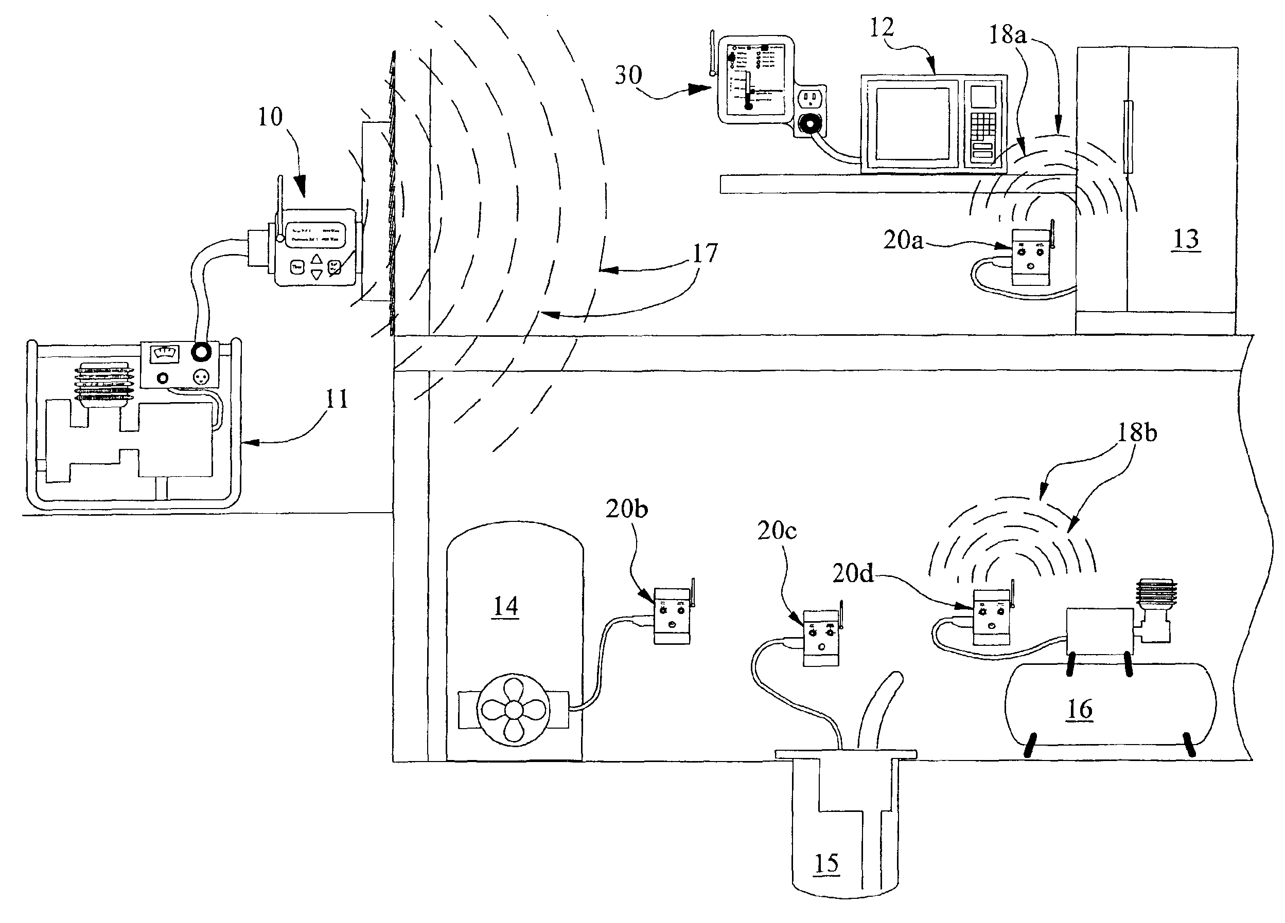
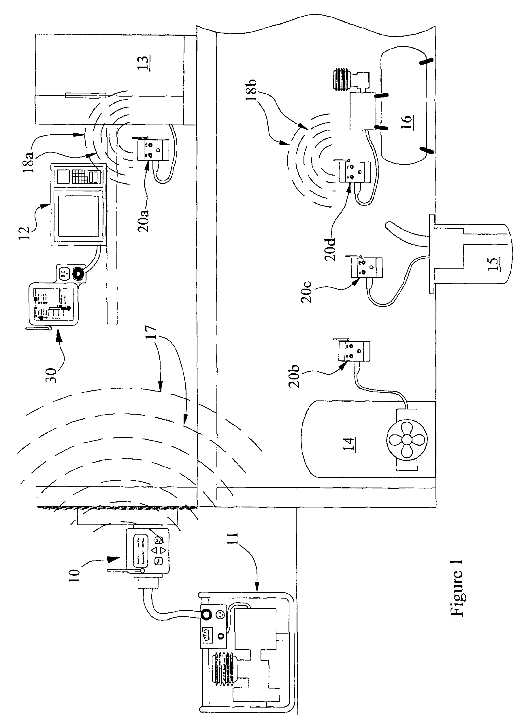
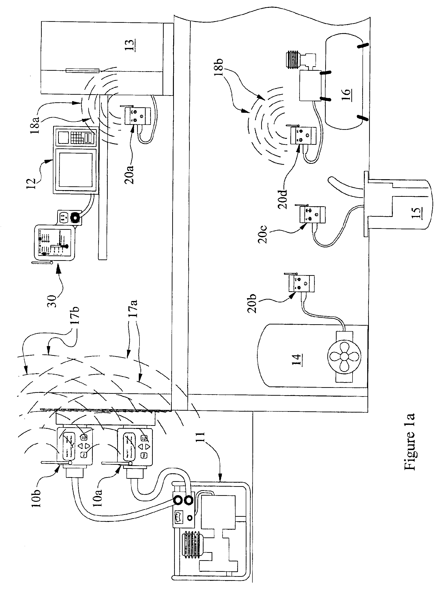
[0005]The embodiment of the invention includes one or more monitoring devices, referred to as “Generator Monitors” which measure the momentary power being used by the home or facility. These generator monitors calculate the remaining power available from the generator and then transmit this available power to the other devices in the system. Each generator monitor transmits the available power to either all or a select group of devices that control the use of
electricity in the home. The other devices in the system, are either an “Interrupt Switch” which controls the power delivered to appliances that turn themselves on and off automatically, or a “User Display” which reports the available power to users that turn on appliances manually, allowing the user to make informed decisions as to whether the appliance can be turned on without overloading the generator. The generator monitors are programmed with the maximum power allowed for the group of appliances monitoring the available power transmissions. The available power is defined as GAP for Generator Available Power. If all the appliances in the home are to have access to the full capacity of the generator, then one generator monitor is configured. If the user decides to allocate a percentage of the generator capacity to a group of appliances (i.e. water pump, furnace and refrigerator) and allocate the balance of the generator capacity to the remaining appliances, then two generator monitors are configured. Multiple generator monitors provide the user a greater level of control over the generator's power.
[0012]The at least one load control may comprise an interrupt switch for interrupting the supply of power to the electric load when the transmitted load capability is less than a predetermined level. The interrupt switch interrupts the supply of power for an interrupt time period upon the return of power following a power failure condition. The interrupt time period is preferably set to
delay the return of power for a period of time for the purpose of reducing the total sudden load on the main power source at initial power return. The interrupt switch may further monitor
electric power levels drawn by the at least one electric load and interrupt the supply of power to the electric load when the transmitted load capability is less than the monitored power levels of the at least one electric load. The interrupt switch may further
delay interruption of the supply of power until the electric load has completed an operation cycle and may further
delay interruption of the supply of power until the electric load has completed an operation cycle if the electric load's continuous load level is substantially equal to a predetermined level of normal operation.
[0016]Load capability may be determined based on a transmitted reference output
signal intended to reduce
power consumption during
peak load or reduced power conditions.

