Shielded flat cable, manufacturing method therefor and machining apparatus therefor

a flat cable and shielding technology, applied in the direction of flat/ribbon cables, insulated conductors, cables, etc., can solve the problem of degrading shielding performan

Inactive Publication Date: 2002-02-21
AUTONETWORKS TECH LTD +2
View PDF0 Cites 93 Cited by
  • Summary
  • Abstract
  • Description
  • Claims
  • Application Information

AI Technical Summary

Problems solved by technology

Consequently, this conventional shielded flat cable has a problem that the shielding performance is degraded owing to the exfoliation of the metallic foils 62a and 62b.
This causes a problem that uniformity of impedance in the longitudinal directi

Method used


Image

  • Shielded flat cable, manufacturing method therefor and machining apparatus therefor
  • Shielded flat cable, manufacturing method therefor and machining apparatus therefor
  • Shielded flat cable, manufacturing method therefor and machining apparatus therefor

Examples


Embodiment Construction

[0072] Embodiments of the present invention are described hereinafter by referring to the accompanying drawings.

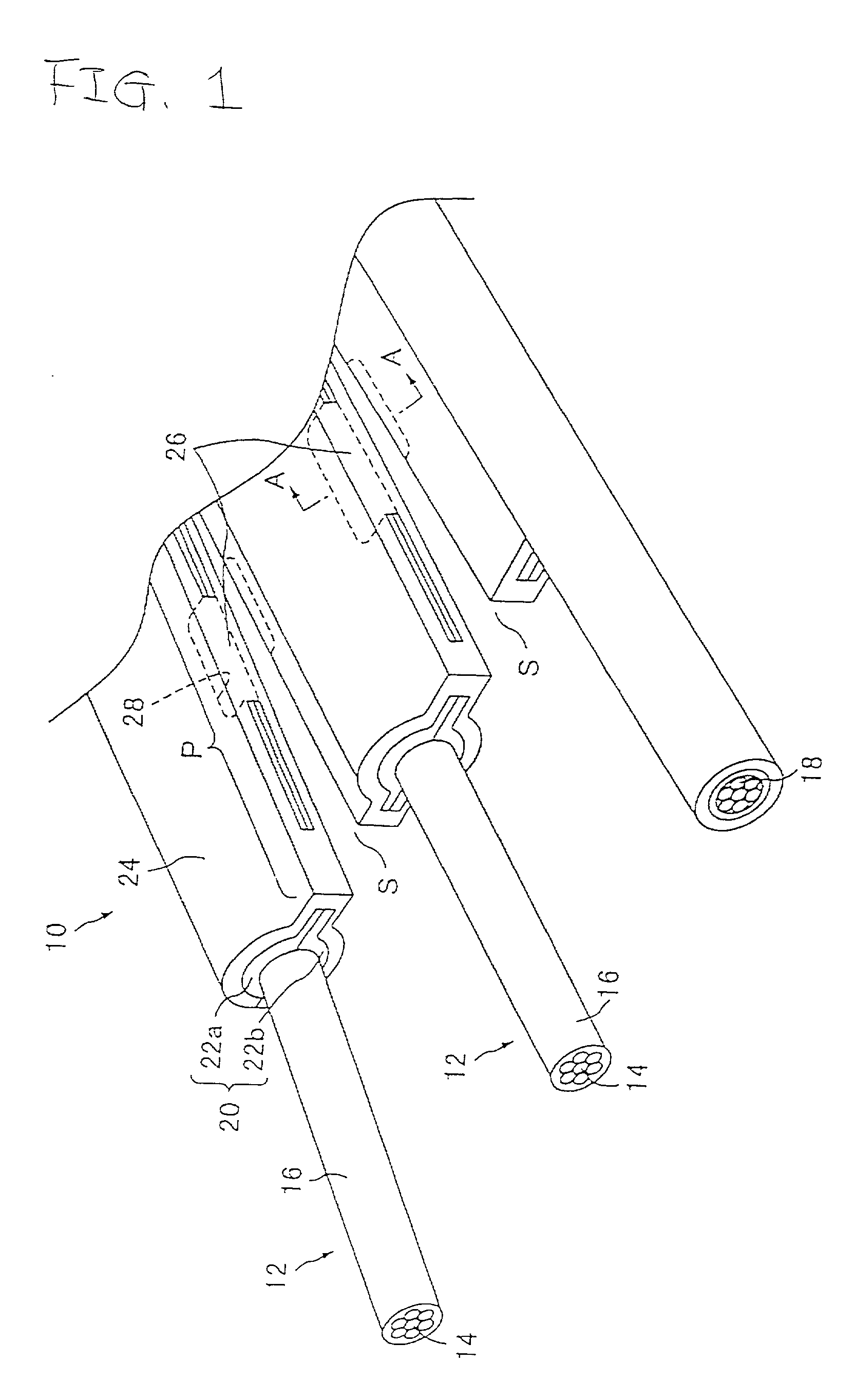
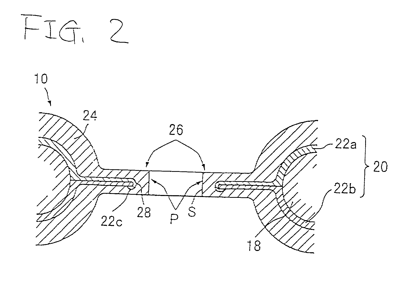
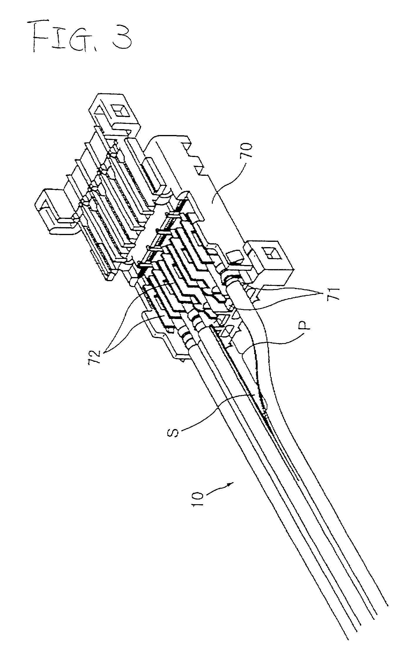
[0073] FIG. 1 is a perspective sectional view illustrating a shielded flat cable 110 according to the present invention. FIG. 2 is a sectional view taken on line A-A, which illustrates the shield structure of the shielded flat cable. Further, FIG. 3 is a perspective view illustrating an example of the use of the shielded flat cable 10 of FIG. 1. The shielded flat cable 10 illustrated in these figures has a plurality of coated wires 12, each of which is constituted by conductors 14 coated with an insulator 16, and drain wires 18 constituted only by conductors. These core wires (the coated wires 12 and the drain wires 18 in this embodiment) are arranged on the same plane in such a manner as to be in parallel with one another. The shield 20 and the external sheath 24 are formed therearound in such a manner as to be integrated therewith. In the case of the illustrated embodime...


PUM


Abstract

A flat cable 10 is constituted by integrally forming a shield 20 and an external sheath 24 with a plurality of core wires 12 and 18. Then, a slit S for branching each of the core wires 12 and 18 is formed at a terminal of the flat cable 10. Further, a coupling portion 26 is formed at a part P in which this slit S is formed. The coupling portion 26 is a means for mechanically coupling the shield 20 thereto. Preferably, the coupling portion 26 is constituted by an external sheath 24 for riveting the shield 20 thereto by penetrating the shield 20 and then connecting the shield 20 thereto.

Description

[0001] 1. Field of the Invention[0002] The present invention generally relates to a shielded flat cable and, more particularly, to a shielded flat cable having a shield formed in such a manner as to integrally cover a plurality of electric wires, and to a method of manufacturing thereof, and to a machining apparatus therefor.[0003] 2. Description of the Related Art[0004] For example, a shielded flat cable of the aforementioned type illustrated in FIG. 24 has been developed. This shielded flat cable is constructed so that a plurality of coated wires 52, each of which is obtained by coating a conductor 54 with an insulator 56, and a plurality of drain wires 58 constituted only by conductors are arranged on the same plane in parallel with one another, that these wires 52 and 58 (hereunder, these wires 52 and 58 will be referred to generically as "core wires") are covered with a shield 60, which is conducted only to the drain wires 58, and that the shield 60 is covered with an insulativ...

Claims


Application Information

Patent Timeline
IPC IPC(8): H01B7/00H01B7/08H01B13/00H01R9/05
CPCH01B7/0861H01R9/0518H01R12/594
Inventor SUZUKI, TOSHIAKI
Owner AUTONETWORKS TECH LTD
Why Eureka
Try Eureka