Seat

a seat and seat technology, applied in the field of seats, can solve the problems of adjusting mechanism noise, unfavorable seat-adjusting mechanism adjustment, and spindle unit being jammed against the end stop of the seat-adjusting mechanism,

Inactive Publication Date: 2002-02-21
BAYERISCHE MOTOREN WERKE AG
View PDF0 Cites 17 Cited by
  • Summary
  • Abstract
  • Description
  • Claims
  • Application Information

AI Technical Summary

Problems solved by technology

The known seat-adjusting mechanisms have numerous disadvantages, including undesired jamming of the spindle unit against the end stops of the seat-adjusting mechanisms.
Furthermore, the adjusting noises of seat-adjusting m

Method used


Image

  • Seat
  • Seat
  • Seat

Examples


Embodiment Construction

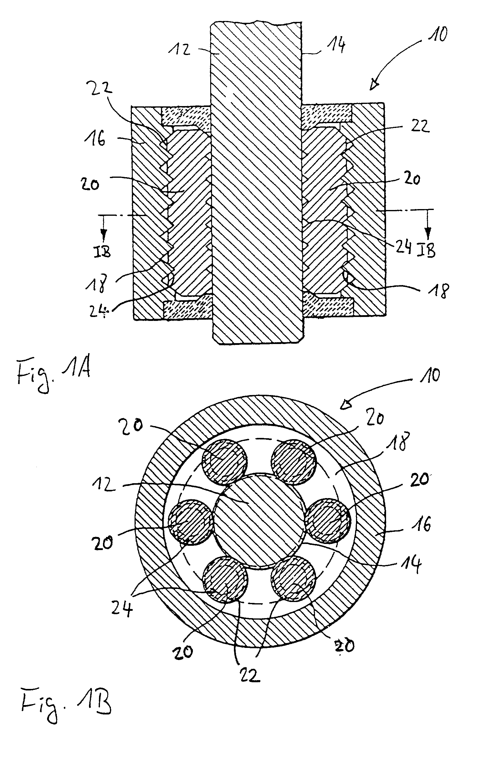
[0031] FIGS. 1A and 1B show a first exemplary embodiment of a spindle unit 10 suitable for incorporation into a seat according to the invention. FIG. 1A shows an axial section through the spindle unit 10 and FIG. 1B shows a section along the line IB-IB in FIG. 1A. A spindle unit of this type is disclosed for example in EP 0 320 621 B1 herewith incorporated by reference. In the case of a seat according to the invention, it is possible to provide a spindle unit having all the features disclosed in EP 0 320 621 B1.

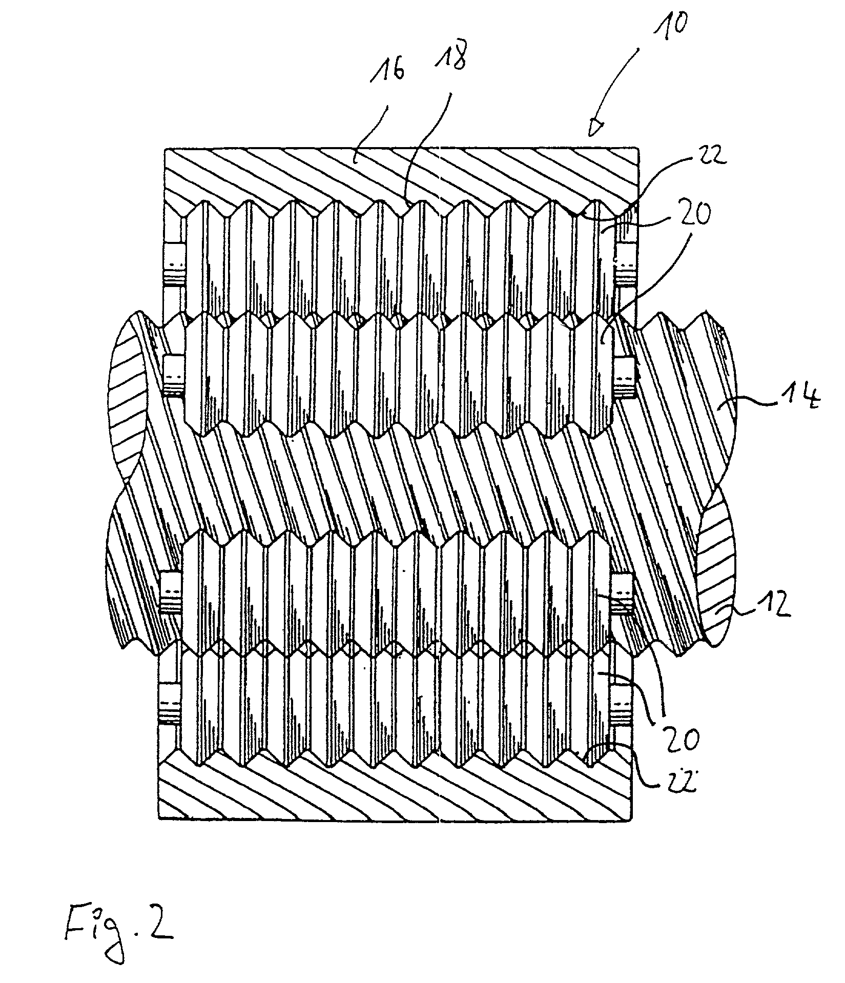
[0032] The spindle unit 10 illustrated in FIGS. 1A and 1B comprises a spindle 12 having an outer thread 14 and a hollow cylindrical nut 16 which surrounds the outside of the spindle 12 radially and has a plurality of coarse V-shaped grooves 18. Six rollers 20 are arranged in planetary manner between the spindle 12 and the nut 16. Each of the rollers 20 has two different, radially outer profiled portions in the form of a first grooved profile 22 and a second grooved profile 24...


PUM


Abstract

A seat, in particular a motor-vehicle seat, having a seat-adjusting mechanism is described. The seat-adjusting mechanism comprises a motor-driven spindle unit with a nut which has an inner profiled portion and a spindle which has an outer profiled portion. The spindle unit comprises a plurality of rollers which are arranged in planetary manner between the nut and the spindle and cooperate with the nut and the spindle. Each of the rollers has at least one outer profiled portion.

Description

[0001] 1. Technical Field[0002] The invention relates to a seat, in particular a motor-vehicle seat, having a seat-adjusting mechanism comprising a motor-driven spindle unit, the spindle unit having a nut which has an inner profiled portion and a spindle which has an outer profiled portion.[0003] 2. Discussion of the Prior Art[0004] Seat-adjusting mechanisms are known which have a motor, a reducing gear and a spindle unit for converting a rotary movement into an axial movement. The spindle unit of such a seat-adjusting mechanism comprises a nut having an inner profiled portion and a spindle which is arranged inside the nut and cooperates with the nut. The spindle is provided with an outer profiled portion which is in engagement with the inner profiled portion of the nut.[0005] The known seat-adjusting mechanisms have numerous disadvantages, including undesired jamming of the spindle unit against the end stops of the seat-adjusting mechanisms. Furthermore, the adjusting noises of sea...

Claims


Application Information

Patent Timeline
IPC IPC(8): B60N2/02B60N2/06B60N2/16B60N2/22
CPCB60N2/0232B60N2/067B60N2/164B60N2/22F16H25/2252B60N2002/0236B60N2/02253B60N2/02246
Inventor LEIN, RUDOLFANGERER, SIEGFRIEDGOMBERT, BERNDGREBENSTEIN, MARKUS
Owner BAYERISCHE MOTOREN WERKE AG
Why Eureka
Try Eureka