High resolution current sensing apparatus

a current sensing apparatus and high-resolution technology, applied in the direction of dc-ac conversion measurement, code conversion, instruments, etc., can solve the problems of increasing the overall system price of the system, the unit cost of state-of-the-art current sensors, and the inability to use analogly for resolutions higher

Inactive Publication Date: 2002-02-21
ROCKWELL AUTOMATION TECH
View PDF0 Cites 21 Cited by
  • Summary
  • Abstract
  • Description
  • Claims
  • Application Information

AI Technical Summary

Benefits of technology

[0013] The technique provides significantly enhanced resolution as compared to heretofore known devices. For example, a current sensor in accordance with the present technique may provide output resolution of 12-16 bits over an operating range of 4-20ma. It does not require a floating power supply, and analog inputs from single modules may be isolated from one another without additional expense Where desired, arrays of large numbers of the modules may be easily formed and coupled to one another for enhanced performance

Problems solved by technology

However, opto-isolators used in such devices are, in general, unsuitable for use in an analog fashion for resolutions higher than 6-8 bits, due to their temperature dependency and drift.
An important drawback in present state-of-the-art current sensors is their unit cost.
Even in applications where a single current sensor suffices for feedback or control, sensors of the type described above can add significantly to the overall system price.
Still further drawbacks in existing technologies include inconsistencies in device-to-device performance, in compatibility with microelectronics, parasitic losses, and the physical dimensions of the current sensor and associated circuitry.
These and the foregoing drawbacks can farther lead to problems with energy dissipation, heating and other thermodynamic and performance problems.

Method used


Image

  • High resolution current sensing apparatus
  • High resolution current sensing apparatus
  • High resolution current sensing apparatus

Examples


Embodiment Construction

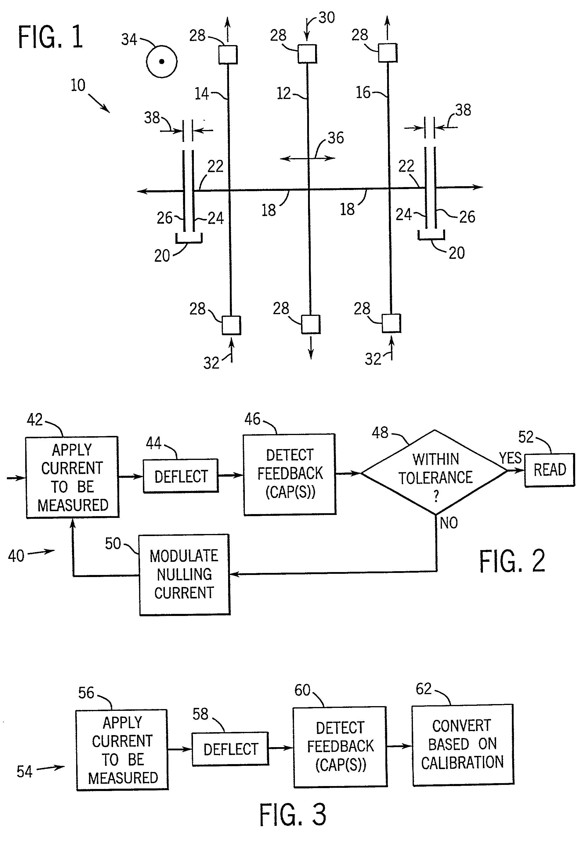
[0023] Turning now to the drawings, and referring first to FIG. 1, a current sensing module 10. in accordance with certain aspects of the present invention is illustrated diagrammatically. The current sensing module of FIG. 1 is designed to receive both a sensed or to be measured current and a nulling current, and to produce signals indicative of balance between the measured and nulling currents. As described below, the device may be adapted to measure current directly without nulling, in an open-loop manner. The closed-loop configuration of FIG. 1, however, includes a measurement beam 12 flanked by a pair of nulling beams 14 and 16 Beams 12, 14 and 16 are deflectable by virtue of their inherent elasticity under the influence of electric currents flowing in the presence of a magnetic field.

[0024] Measurement beam 12 and nulling beams 14 and 16 are mechanically coupled to one another by a pair of connecting members 18. Connecting members 18 permit forces tending to deflect beams 12, ...


PUM


Abstract

A current sensor includes a deflectable member disposed in a magnetic field. Nulling or compensating members may be mechanically coupled to the deflectable member, Feedback or readout devices coupled to the structure provide signals indicative of deflection of the deflectable member under the influence of applied current and the magnetic field. Nulling current applied to the nulling members tends to oppose deflection of the deflectable member. The nulling current may be modulated to drive the feedback signal to a desired level and is used as a basis for calculating the current to be measured. The current may be measured directly upon calibration of feedback devices coupled to the deflectable member or to the nulling members. Arrays of sensors may be coupled to common busses for applying measured and nulling currents to sensors of the arrays and for detecting feedback signals.

Description

[0001] 1. Field of the Invention[0002] The present invention relates generally to the field of electrical current sensing devices such as those used in programmable logic controllers and other environments. More particularly, the invention relates to a technique for sensing current with very high resolution in a device which can be at least partially formed in large quantities through micro-machining and similar techniques.[0003] 2. Description of the Related Art[0004] A wide range of applications exist for devices capable of accurately sensing electrical current. In certain applications, current is sensed for simple readout, such as on a metered scale or digital display. A considerable number of applications, however, require current to be sensed for use in regulation of power or as feedback for the control of machines, circuits, and processes,.[0005] In the industrial environment, for example, feedback devices and actuators typically operate within specified current and voltage ra...

Claims


Application Information

Patent Timeline
Patent Type & Authority Applications(United States)
IPC IPC(8): G01R15/18G01R17/08G01R19/20
CPCG01R15/185G01R17/08G01R19/20G01R33/0286
Inventor YAO, JUN JASONSULLIVAN, GERARD J.ANDERSON, ROBERT J.
Owner ROCKWELL AUTOMATION TECH
Why Eureka
Try Eureka