Chemico-mechanical microvalve and devices comprising the same

a micro-fluidic and mechanical technology, applied in chemical/physical/physico-chemical microreactors, optical light guides, fluid speed measurement, etc., can solve the problems of inability to control the valve, significant technical obstacles to overcome, and control of fluid flow

Inactive Publication Date: 2002-05-09
ROBOTTI KARLA M +2
View PDF12 Cites 188 Cited by
  • Summary
  • Abstract
  • Description
  • Claims
  • Application Information

AI Technical Summary

Problems solved by technology

Despite the potential advantages provided by such devices, there are still significant technical obstacles that must be overcome if such devices are ever to realize their full potential.
One such obstacle is the control of fluid flow, particularly between various regions or compartments in the device, i.e. control of fluid flow at the micro / micro interface level.
However, there are significant drawbacks associated with each of these proposals, which drawbacks include: inability to control the valve, lack of sufficiently strong materials, lack of ability to sufficiently seal the valve, etc.

Method used


Image

  • Chemico-mechanical microvalve and devices comprising the same
  • Chemico-mechanical microvalve and devices comprising the same
  • Chemico-mechanical microvalve and devices comprising the same

Examples


first embodiment

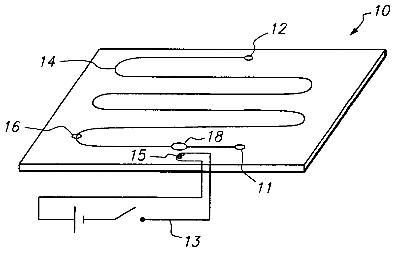
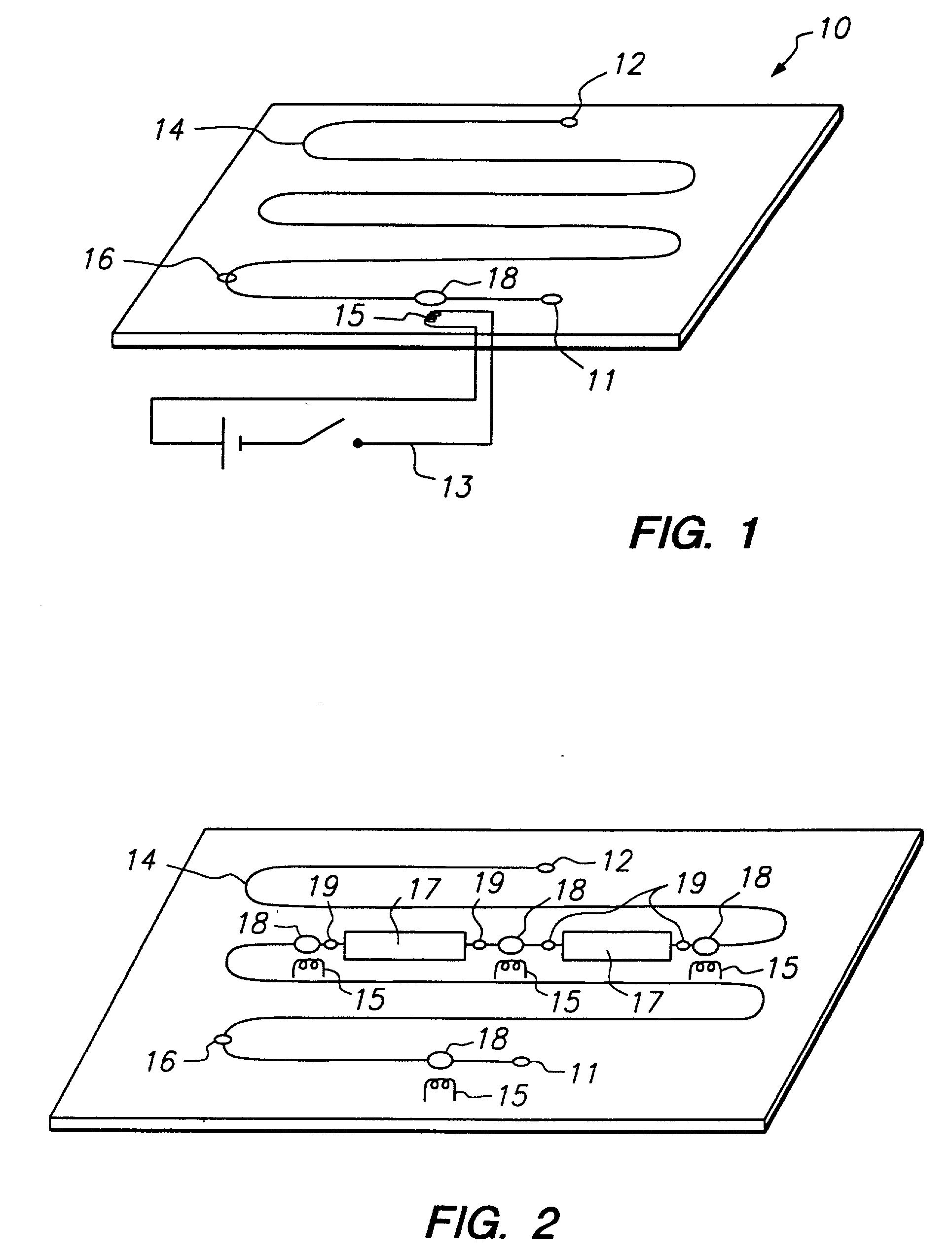
[0036] In the subject invention, the micro-valve is made solely of the phase reversible material. In this embodiment, the phase reversible material may be positioned at one or more distinct locations along the fluid flow path, or along substantially the entire fluid flow path. Where the phase-reversible material occupies substantially the entire fluid flow path, during use its phase is generally switched from a fluid permeable to a fluid impermeable state at one or more distinct locations along the fluid flow path, but not along the entire fluid flow path.

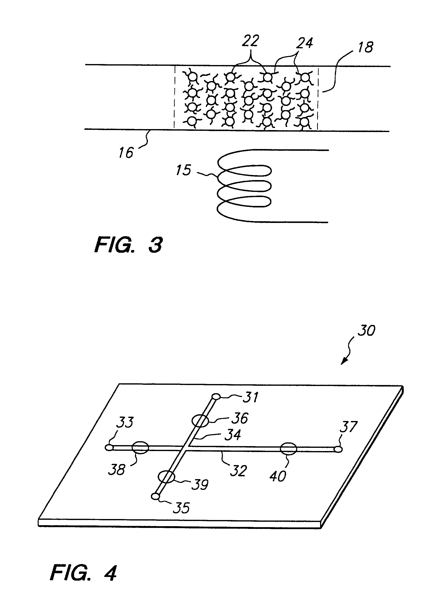
[0037] In a preferred structure of the this first embodiment, the micro-fluidic device contains at least two intersecting flow paths, one of which is substantially filled by the phase reversible material. In other words, the device includes at least a main flow path and at least one intersecting second flow path, where substantially all of the secondary flow path is occupied by the phase reversible material. By "substantially all" ...

second embodiment

[0039] In these embodiments where the micro-valve consists essentially of the phase reversible material, the phase reversible material will be stably associated with the region of the device in which fluid flow modulation is desired. Stable association may be achieved in a number of ways, including bonding, and the like. In many embodiments, the phase reversible material may be bonded directly to the region of interest of the micro-fluidic device, where the nature of the bond may be covalent or non-covalent. For example, where the phase reversible material is a polymeric gel, the polymeric constituents of the phase reversible material may be bonded directly to the micro-compartment wall of the device in the region in which valve fluid control is desired, where the nature of the bond may be covalent or non-covalent, but will usually be covalent. The length of the micro-compartment occupied by the micro-valve in this second embodiment, i.e. the length of the micro-compartment to which...


PUM

PropertyMeasurementUnit
micro-volumeaaaaaaaaaa
volumeaaaaaaaaaa

Abstract

Micro-fluid devices and methods for their use are provided. The subject devices are characterized by the presence of at least one micro-valve comprising a phase reversible material, e.g. a reversible gel, that reversibly changes its physical state in response to an applied stimulus, e.g. a thermoreversible gel. In using the subject device, fluid flow along a flow path of the device is modulated by applying an appropriate stimulus, e.g. changing the temperature, to the microvalve. The subject devices find use in a variety of applications, including micro-analytical applications.

Description

[0001] Pursuant to 35 U.S.C. .sctn. 119 (e), this application claims priority to the filing date of the U.S. Provisional Patent Application Serial No. 60 / 091,093 filed Jun. 29, 1998, the disclosure of which is herein incorporated by reference.[0002] 1. Technical Field[0003] The field of this invention is micro-fluidic devices.[0004] 2. Background of the Invention[0005] Many important chemical processes are carried out in fluid environments, where such processes include chemical syntheses, fluid sample analyses, fluid component separations, and the like. In many situations, it is desirable to work with small volumes of fluid, e.g. from femtoliter to .mu.l quantities of fluid. Such situations include sample analysis in which small volumes of initial sample are analyzed; chemical synthesis, in which small quantities of chemical are desired and / or expensive reagents are employed, and the like. As such, there has been much interest in the development of micro-fluidic devices in which flu...

Claims


Application Information

Patent Timeline
Patent Type & Authority Applications(United States)
IPC IPC(8): B01J19/00B01L3/00B81B1/00B81B3/00F15C5/00F16K99/00
CPCB01J19/0093Y10T436/2575B01J2219/00907B01J2219/00909B01L3/502738B01L2300/0816B01L2300/087B01L2400/0677B81B3/0035F16K99/0001F16K99/0017F16K99/0025F16K99/0036F16K99/0044F16K2099/0074F16K2099/0076F16K2099/0078F16K2099/0084B01J2219/00891Y10T137/2082
Inventor ROBOTTI, KARLA M.SWEDBERG, SALLY A.YIN, HONGFENG
Owner ROBOTTI KARLA M
Why Eureka
Try Eureka