Transformer and electrical device using the same
- Summary
- Abstract
- Description
- Claims
- Application Information
AI Technical Summary
Problems solved by technology
Method used
Image

Examples
second embodiment
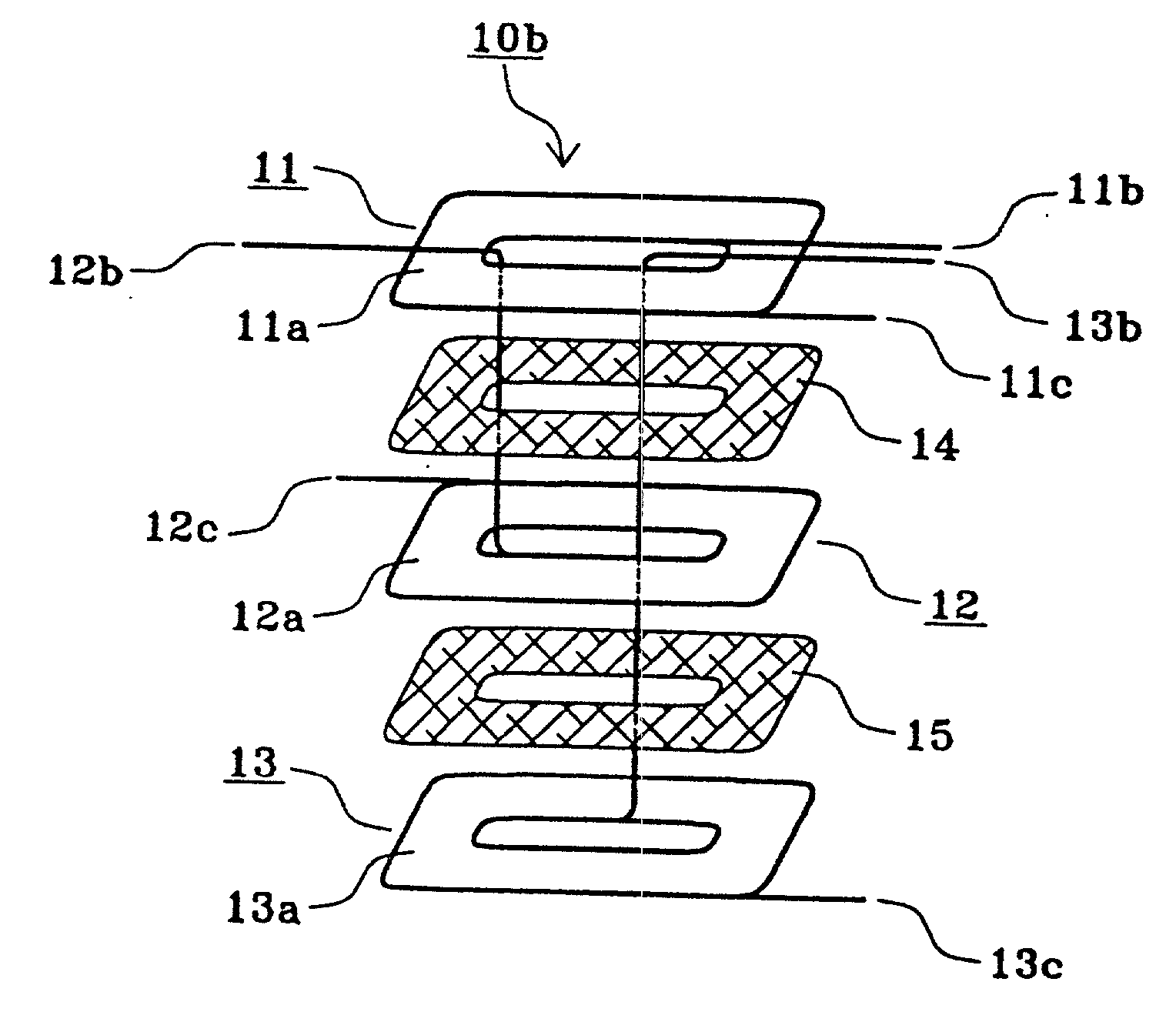
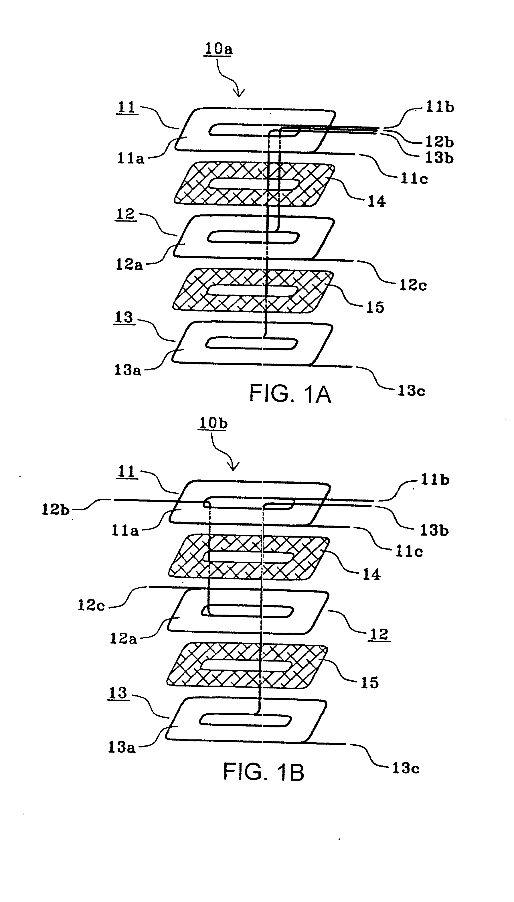
[0035] Although in the transformer 10a shown in FIG. 1A, the inner ends 11b, 12b, and 13b of the flat coils 11, 12, and 13, respectively, are drawn out over the outer surface (upper side) of the outermost flat coil 11, the inner ends 11b, 12b, and 13b may be drawn out over the outer surface (lower side) of the outermost flat coil 13. The inner ends 11b, 12b, and 13b may be drawn out between the flat coils 11 and 12 or between the flat coils 12 and 13. The inner ends 11b, 12b, and 13b may be drawn out in directions differing from each other, as in a transformer 10b shown in FIG. 1B, as long as the inner ends 11b, 12b, and 13b are each disposed on the same surface of one of the flat coils 11, 12, and 13. When the inner ends 11b, 12b, and 13b are drawn out between two of the flat coils 11, 12, and 13, an insulative film may be provided between the corresponding flat coil 11, 12, or 13 and the inner ends 11b, 12b, and 13b, as needed.
third embodiment
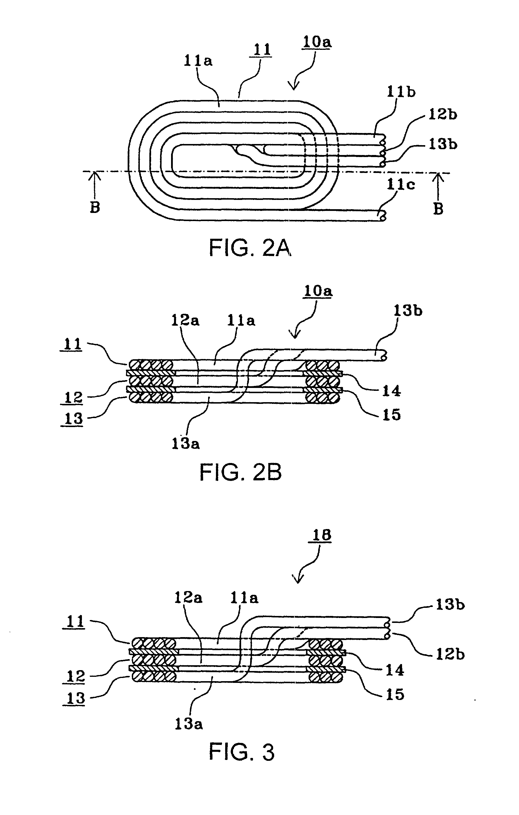
[0036] FIG. 3 is a sectional view of a transformer according to the present invention. The transformer is shown in section along a line corresponding to the line B-B of the transformer 10a shown in FIG. 2A. Components the same as or corresponding to those which are shown in FIGS. 2A and 2b are referred to with the same reference numerals, for which description is omitted.
[0037] In a transformer 18 shown in FIG. 3, the inner end 13b of the wire 13a forming the flat coil 13 is drawn to the outside of the transformer 18 through the respective holes for passing a magnetic core-leg of the insulative sheet 15, the flat coil 12, the insulative sheet 14, and the flat coil 11 and over the inner ends 11b and 12b of the flat coils 11 and 12, respectively. That is, the inner ends 11b and 12b of the flat coils 11 and 12, respectively, are disposed on the same surface of the flat coil 11, and the inner end 13b of the flat coil 13 is disposed on the inner ends 11b and 12b.
[0038] In the thus formed...
fourth embodiment
[0041] FIG. 4 is an exploded perspective view of a transformer according to the present invention, in which components the same as or corresponding to those of the transformers 10a and 10b shown in FIGS. 1A and 1B, respectively, are referred to with the same reference numerals, for which description is omitted.
[0042] In a transformer 20 shown in FIG. 4, the inner ends 11b and 13b of the wire 11a and 13a forming the flat coils 11 and 13 are drawn to the outside of the transformer 20 over a wound portion of the wire 11a forming the flat coil 11, the inner end 13b being drawn through the respective holes for passing a magnetic core-leg of the insulative sheet 15, the flat coil 12, the insulative sheet 14, and the flat coil 11. That is, only the inner ends 11b and 13b of the flat coils 11 and 13, respectively, are disposed on the same surface of the flat coil 11. The inner end 12b of the wire 12a forming the flat coil 12 is drawn to the outside of the transformer 20 between the flat coi...
PUM
 Abstract
Description
Claims
Application Information
 - R&D Engineer
- R&D Manager
- IP Professional
- Industry Leading Data Capabilities
- Powerful AI technology
- Patent DNA Extraction
Browse by: Latest US Patents, China's latest patents, Technical Efficacy Thesaurus, Application Domain, Technology Topic.
© 2024 PatSnap. All rights reserved.Legal|Privacy policy|Modern Slavery Act Transparency Statement|Sitemap