
Wheel drive unit

a technology of drive unit and drive shaft, which is applied in the direction of coupling, rigid support of bearing unit, transportation and packaging, etc., can solve the problem that the properties of each constituent element have not been considered optimally

Inactive Publication Date: 2002-06-13
NSK LTD
View PDF0 Cites 30 Cited by
  • Summary
  • Abstract
  • Description
  • Claims
  • Application Information

AI Technical Summary

Problems solved by technology

However with regards to this point, heretofore no consideration has been given to make the properties of each constituent element optimum to deal with these stresses.

Method used


Image

  • Wheel drive unit
  • Wheel drive unit
  • Wheel drive unit

Examples


Embodiment Construction

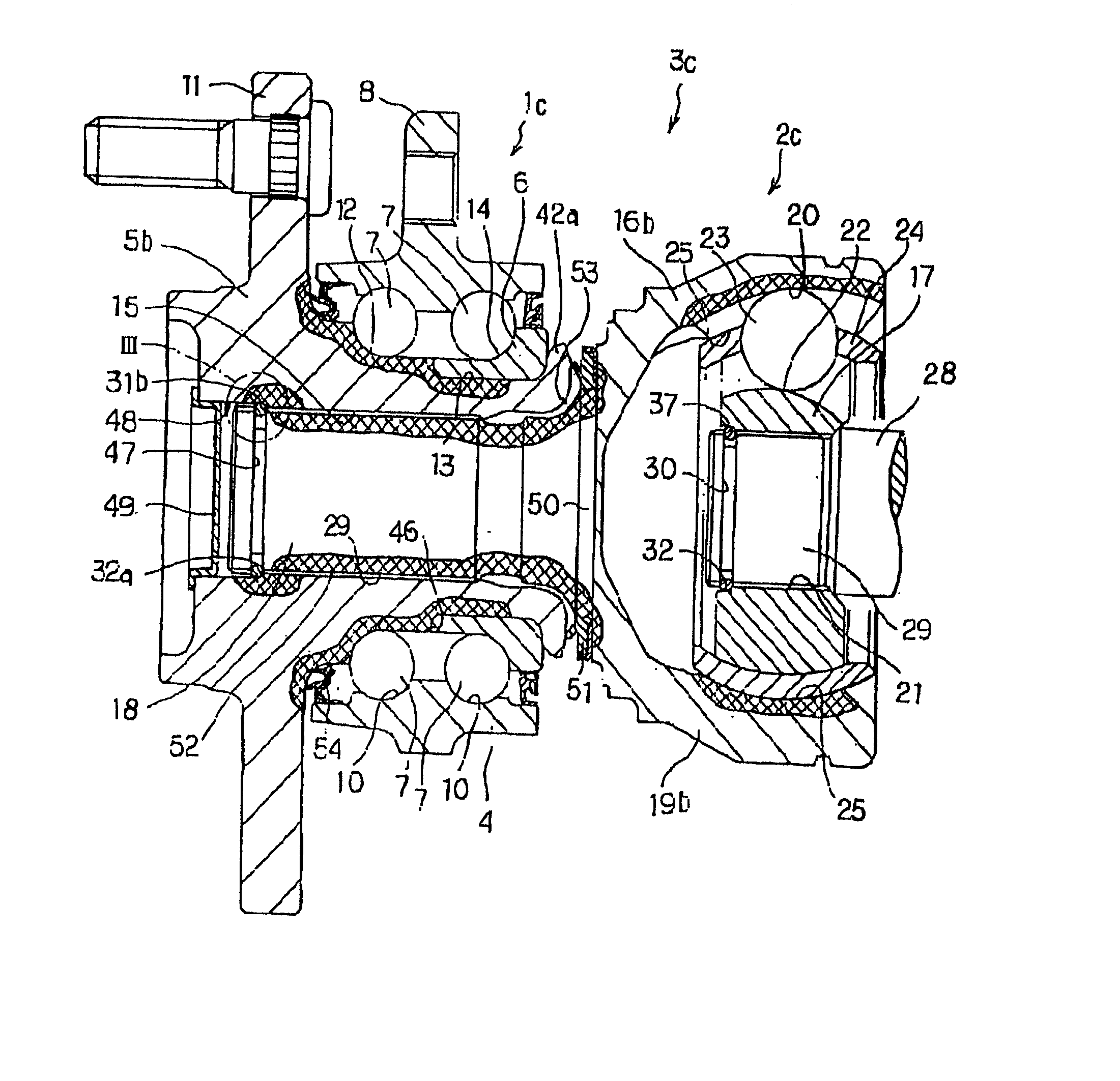
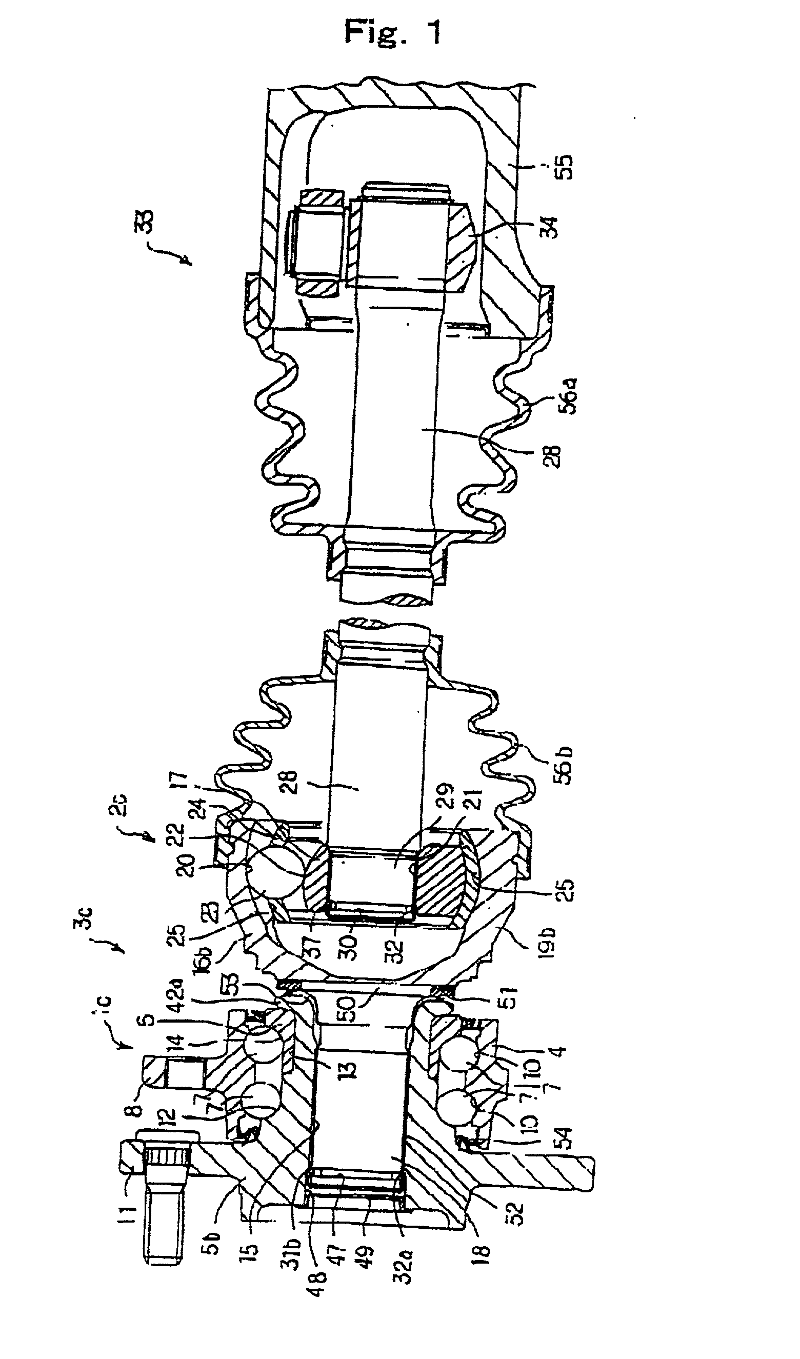
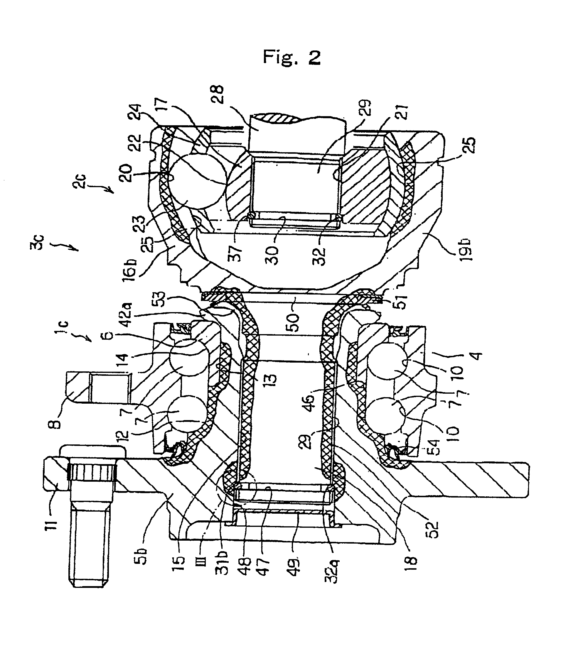
[0028] The wheel drive unit of the present invention comprises a rolling bearing unit for wheel support, a constant velocity joint unit and a snap ring.

[0029] Of these, the constant velocity joint unit has a first constant velocity joint for connecting an input portion thereof to an output portion of a differential gear, a transmission shaft with an input side end portion thereof connected to an output portion of the first constant velocity joint, said a second constant velocity joint with an input portion thereof to an output side end portion of the transmission shaft connected.

[0030] Furthermore, the rolling bearing unit for wheel support has an outer ring, a hollow hub, rolling elements and a first spline portion.

[0031] Of these, the outer ring has a double row of outer ring raceways on an inner peripheral face thereof and does not rotate at the time of use.

[0032] Moreover, the hub is provided with a flange for supporting a vehicle wheel, on a part near an outer end of an outer p...


PUM


Abstract

A wheel drive unit is provided to comprise a bearing unit 3c for wheel drive which is light in weight and low in cost. The components constituting the bearing unit 3c for wheel drive have optimum properties to secure the durability thereof. Of the components constituting the bearing unit 3c for wheel drive, the portions indicated by a diagonal grid hatching are quench-hardened with the other portions being not quench-hardened and left as they are, whereby the rolling fatigue life and wear-resistance of the components are improved and cracking is prevented.

Description

DESCRIPTION[0001] 1. Field of the Invention[0002] The present invention relates to a wheel drive unit which is a combination of a wheel support rolling bearing unit, a constant velocity joint unit and a snap ring, and is used for rotatably supporting with respect to a suspension unit, a driven wheel {the front wheel of a FF vehicle (front engine, front drive wheel) the rear wheel of both a FR vehicle (front engine, rear drive wheel) and a RR vehicle (rear engine, rear drive wheel) and all wheels of a 4WD vehicle (four drive wheel)} supported on an independent suspension type suspension, and for rotationally driving the driven wheel.[0003] 2. Background of the Invention[0004] In order to rotatably support a vehicle wheel with respect to a suspension unit, various kinds of rolling bearing units for wheel support with an outer ring and inner ring assembled so as to be freely rotatable via rolling elements, are used. Moreover, a wheel support rolling bearing unit for supporting a driven...

Claims


Application Information

Patent Timeline
Patent Type & Authority Applications(United States)
IPC IPC(8): B60B27/00F16C19/18F16C33/64B60B35/18F16C35/063F16D1/02F16D3/20F16D3/223
CPCB60B27/00B60B27/0005B60B27/0026B60B27/0042B60B27/0084B60B27/0094Y10S464/906F16C33/64F16D3/223F16D2003/22326F16D2250/00F16D2300/10F16C19/186F16C35/0635F16C2326/02F16C2226/50F16C2240/42F16C19/18Y02T10/86
Inventor OUCHI, HIDEO
Owner NSK LTD
Features
  • Generate Ideas
  • Intellectual Property
  • Life Sciences
  • Materials
  • Tech Scout
  • Unparalleled Data Quality
  • Higher Quality Content
  • 60% Fewer Hallucinations
Learn More