CENTRAL RESEARCH INSTITUTE OF ELECTRIC POWER INDUSTRY +2
View PDF0 Cites 9 Cited by
Summary
Abstract
Description
Claims
Application Information
AI Technical Summary
This helps you quickly interpret patents by identifying the three key elements:
Problems solved by technology
Method used
Benefits of technology
Benefits of technology
[0009] According to the present invention, a hot-water supply system includes a tank for storing hot water for a supply, a water-heating unit operated electrically for heating water by performing boiling operation, and a control unit for controlling the boiling operation of the water-heating unit. The control unit includes use heat-quantity calculating means for calculating a heat quantity used in a predetermined time period based on a hot-water supply amount from the tank in the predetermined time period and for learning the heat quantity used in the predetermined time period, target heat-quantity calculating means for calculating a target heat quantity for boiling based on the learned heat quantity in the use heat-quantity calculating means, target temperature calculating means for calculating a target boiling temperature of water based on the target heat quantity calculated by the target heat-quantity calculating means, and boiling means for performing boiling operation of the water-heating unit by a necessary boiling amount based on the target boiling temperature calculated from the target temperature calculating means. In the hot-water supply system, the boiling operation is performed by the necessary boiling amount, it can prevent a wasteful heat radiation of hot water stored in the tank while preventing a shortage of hot water.
[0010] Preferably, the control unit further includes time-zone heat-quantity calculating means for calculating and learning a heat quantity used in each time zone based on each hot-water supply amount during a plurality of time zones in which power rate are different from each other, present heat-quantity calculating means for calculating a heat quantity stored in hot water within the tank at the present time, shortage estimating means for estimating a shortage of the heat quantity stored in hot water within the tank based on the heat quantity from the time-zone heat quantity calculating means and the heat quantity from the present heat quantity calculating means, and compulsory-boiling means for additionally performing the boiling operation in accordance with a shortage amount of the heat quantity when the shortage is estimated by the shortage estimating means. Accordingly, a shortage of hot water in each time zone can be prevented.
[0011] Preferably, the control unit includes hot-water amount detecting means for detecting a hot-water amount stored in the tank. Further, as the hot-water amount stored in the tank at a start time of the midnight time zone is smaller, the first boiling time period is set longer and the first boiling start time is set earlier. Therefore, the boiling operation can be accurately finished before the finish of the midnight time zone. Accordingly, heat loss in the midnight time zone can be prevented.
Problems solved by technology
However, in the-above-described conventional systems, because a hot-water amount to be stored in the tank is limited, the hot-water amount stored in the midnight time zone becomes insufficient in a home using hot water more than the the hot-water amount stored in the tank in a time zone from the morning to the midnight (e.g., 7:00 to 23:00).
Accordingly, in the time zone of evening or night, hot water may become short.
On the other hand, in a home where a large-amount of hot water is used in one day, a shortage of hot water may be caused.
Method used
Image
Click on the blue label to locate the original text in one second.
Reading with bidirectional positioning of images and text.
Examples
first embodiment
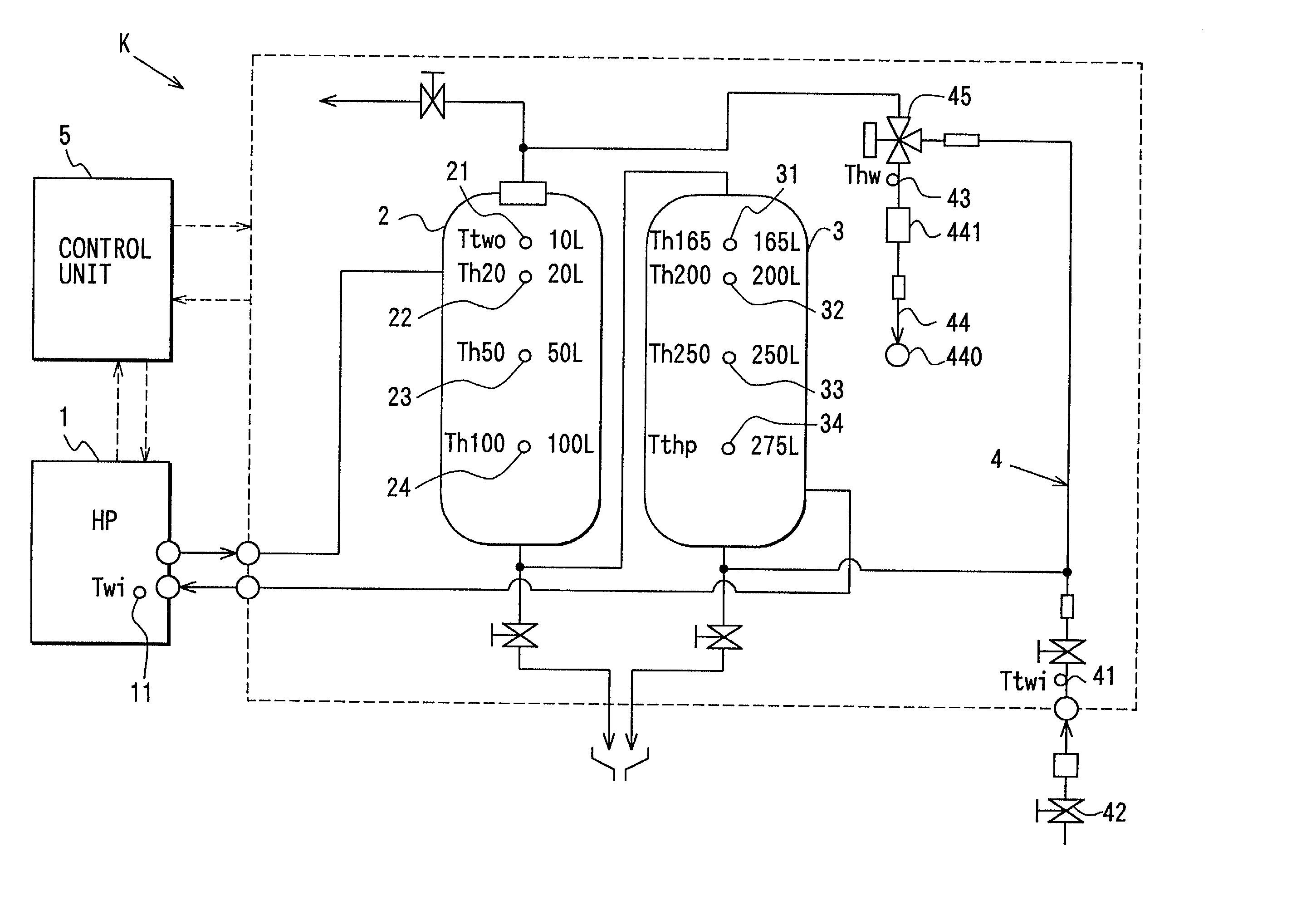
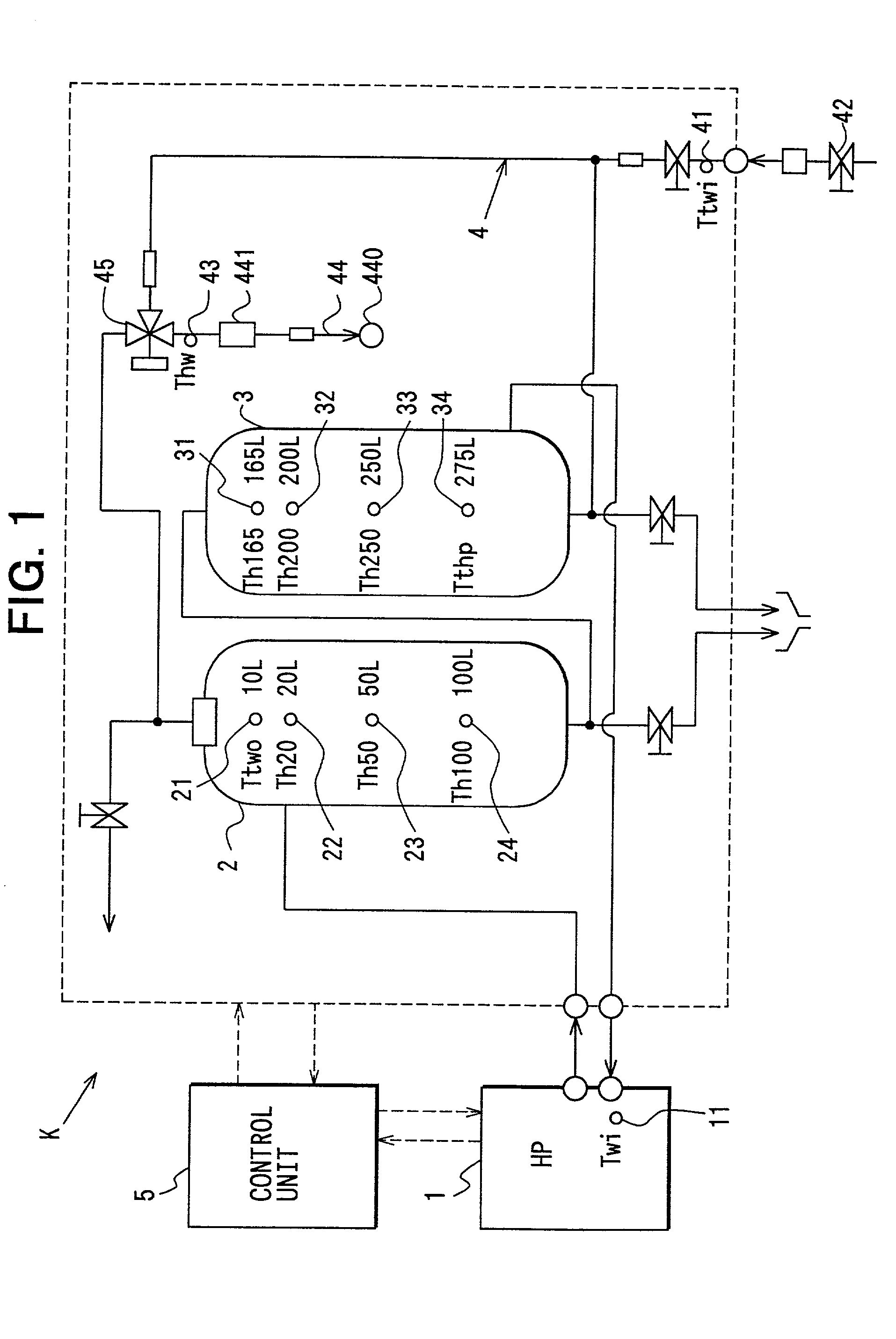
[0028] A first preferred embodiment of the present invention will be now described with reference to FIGS. 1-10. As shown in FIG. 1, a hot-water supply system K includes a heat pump unit (HP unit) 1 for heating water by performing water-heating operation (boiling operation). In the heat pump unit 1, refrigerant is compressed by an electrical compressor, and water is heated by using a condensation heat of refrigerant to have a temperature of about 90.degree. C. in maximum. In the first embodiment, carbon dioxide is used as refrigerant, for example.
[0029] Double-pipe type tanks 2, 3 are disposed to store hot water heated by the heat pump unit 1. By operation (boiling operation) of about 6 hours of the heat pump unit 1, hot water 5 is fully stored in the tanks 2, 3. In the first embodiment, both the tanks 2, 3 are fully filled with hot water of about 300 liters.
[0089] wherein, Lw is the necessary boiling amount in the midnight time zone, and SP is a specific gravity.
[0090] Accordingly, in the third embodiment of the present invention, the heat loss of the stored hot water can be accurately prevented.
fourth embodiment
[0091] A fourth preferred embodiment of the present invention will be now described with reference to FIGS. 13 and 14. As shown in FIG. 13, the heating capacity Q (boiling capacity) is changed in accordance with the water supply temperature Twi. Therefore, an accurate calculation of the general-boiling time period Tw becomes difficult. That is, when hot water remains in the tanks 2, 3, the water supply temperature Trwi is changed in the boiling operation, and the heating capacity Q is changed as shown in FIG. 13, thereby the accurate calculation of the general-boiling time period tw becomes difficult. Thus, in the present invention, the temperature in each tank position is detected 5 by the thermistors 22-24 and 31-34, the water temperature distribution in the tanks 2, 3 is detected, and the hot-water storage amount Lt stored in the tanks 2, 3 is calculated.
[0092] In addition, the mean supply water temperature THWA for the later 24 hours (e.g., from 23:00 of the previous day to 23:0...
PUM
Abstract
In a control unit of a hot-water supplysystem, a boiling time period is estimated based on a hot-water amount stored in a tank at a time of 23:00, a boiling start time is adjusted so that boiling operation is finished at a time immediately before 7:00. For example, when the hot water amount stored in the tank is smaller at the time of 23:00, the boiling time period is made longer and the boiling start time is made earlier. On the other hand, when the hot water amount stored in the tank is larger at the time of 23:00, the boiling time period is made shorter and the boiling start time is made later.
Description
[0001] This application is related to Japanese Patent Application No. 2000-367052 filed on Dec. 1, 2000, the contents of which are hereby incorporated by reference.[0002] 1. Field of the Invention[0003] The present invention relates to a hot-water supplysystem in which water is boiled using electrical power.[0004] 2. Description of Related Art[0005] In a conventional hot-water supplysystem described in JP-B2-2858788 or in JP-B2-63-35904, electrical power is supplied to a heater in a midnighttime zone which is cheapest in power rate, so that water is boiled and a hot-water storage tank is filled up in the midnighttime zone. Specifically, in the conventional system of JP-B2-2858788, an on-off control of an electrical supply to the heater core is performed at different time zones. On the other hand, in the conventional system of JP-B2-63-35904, the supply of the electrical power to the heater starts from a start time of the midnighttime zone.[0006] However, in the-above-described ...
Claims
Application Information
Patent Timeline
Application Date:The date an application was filed.
Publication Date:The date a patent or application was officially published.
First Publication Date:The earliest publication date of a patent with the same application number.
Issue Date:Publication date of the patent grant document.
PCT Entry Date:The Entry date of PCT National Phase.
Estimated Expiry Date:The statutory expiry date of a patent right according to the Patent Law, and it is the longest term of protection that the patent right can achieve without the termination of the patent right due to other reasons(Term extension factor has been taken into account ).
Invalid Date:Actual expiry date is based on effective date or publication date of legal transaction data of invalid patent.

