Hot-water supply system

a technology of hot water supply and supply system, which is applied in the direction of lighting and heating apparatus, heating types, instruments, etc., can solve the problems of shortening the hot water supply time, insufficient hot water storage in the midnight time zone, and causing shortages of hot water

Inactive Publication Date: 2003-09-30
CENTRAL RESEARCH INSTITUTE OF ELECTRIC POWER INDUSTRY +2
View PDF11 Cites 31 Cited by
  • Summary
  • Abstract
  • Description
  • Claims
  • Application Information

AI Technical Summary

Benefits of technology

According to the present invention, a hot-water supply system includes a tank for storing hot water for a supply, a water-heating unit operated electrically for heating water by performing boiling operation, and a control unit for controlling the boiling operation of the water-heating unit. The control unit includes use heat-quantity calculating means for calculating a heat quantity used in a predetermined time period based on a hot-water supply amount from the tank in the predetermined time period and for learning the heat quantity used in the predetermined time period, target heat-quantity calculating means for calculating a target heat quantity for boiling based on the learned heat quantity in the use heat-quantity calculating means, target temperature calculating means for calculating a target boiling temperature of water based on the target heat quantity calculated by the target heat-quantity calculating means, and boiling means for performing boiling operation of the water-heating unit by a necessary boiling amount based on the target boiling temperature calculated from the target temperature calculating means. In the hot-water supply system, the boiling operation is performed by the necessary boiling amount, it can prevent a wasteful heat radiation of hot water stored in the tank while preventing a shortage of hot water.
Preferably, the control unit further includes time-zone heat-quantity calculating means for calculating and learning a heat quantity used in each time zone based on each hot-water supply amount during a plurality of time zones in which power rate are different from each other, present heat-quantity calculating means for calculating a heat quantity stored in hot water within the tank at the present time, shortage estimating means for estimating a shortage of the heat quantity stored in hot water within the tank based on the heat quantity from the time-zone heat quantity calculating means and the heat quantity from the present heat quantity calculating means, and compulsory-boiling means for additionally performing the boiling operation in accordance with a shortage amount of the heat quantity when the shortage is estimated by the shortage estimating means. Accordingly, a shortage of hot water in each time zone can be prevented.
Preferably, the control unit includes hot-water amount detecting means for detecting a hot-water amount stored in the tank. Further, as the hot-water amount stored in the tank at a start time of the midnight time zone is smaller, the first boiling time period is set longer and the first boiling start time is set earlier. Therefore, the boiling operation can be accurately finished before the finish of the midnight time zone. Accordingly, heat loss in the midnight time zone can be prevented.

Problems solved by technology

However, in the-above-described conventional systems, because a hot-water amount to be stored in the tank is limited, the hot-water amount stored in the midnight time zone becomes insufficient in a home using hot water more than the the hot-water amount stored in the tank in a time zone from the morning to the midnight (e.g., 7:00 to 23:00).
Accordingly, in the time zone of evening or night, hot water may become short.
On the other hand, in a home where a large-amount of hot water is used in one day, a shortage of hot water may be caused.

Method used


Image

  • Hot-water supply system
  • Hot-water supply system
  • Hot-water supply system

Examples


first embodiment

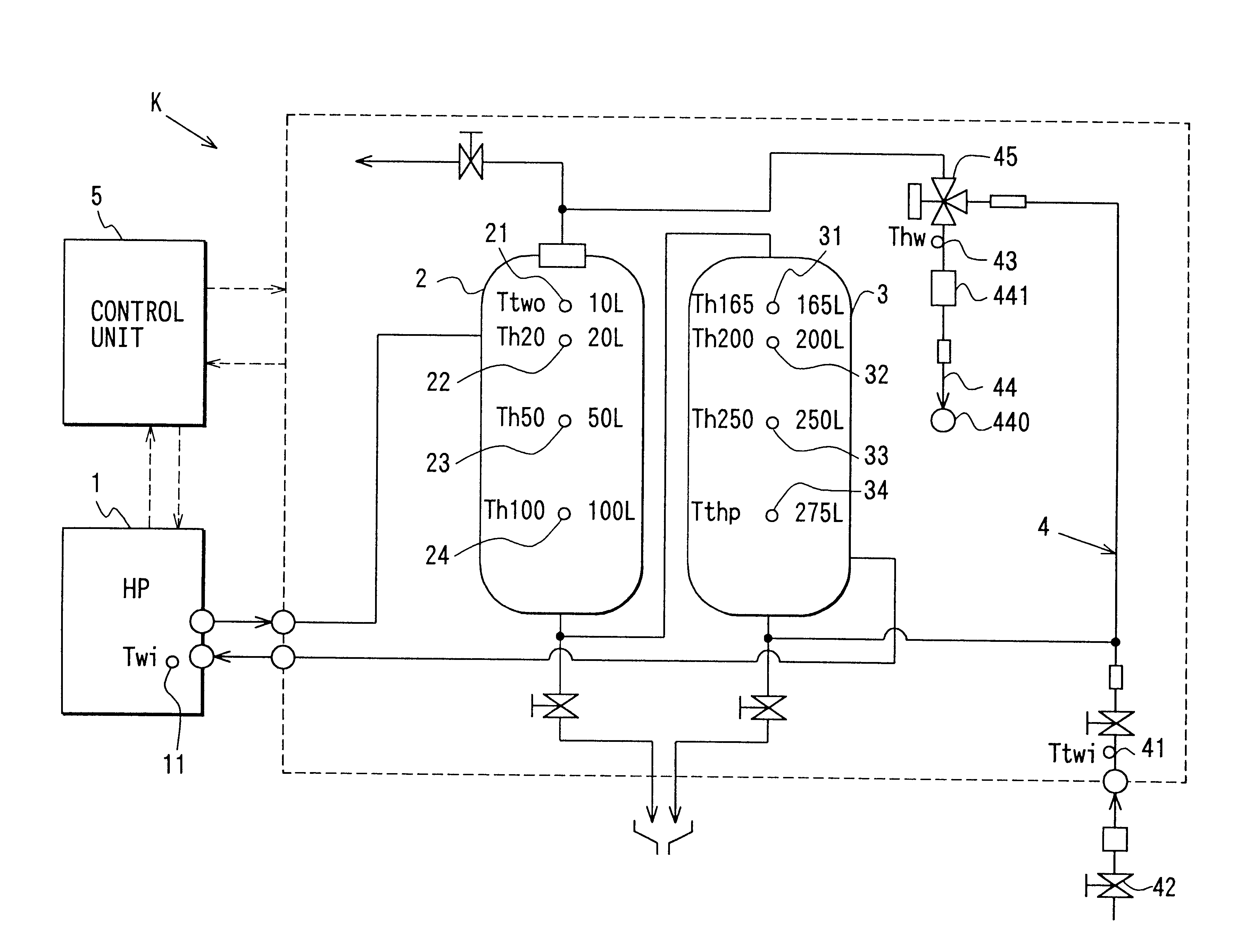
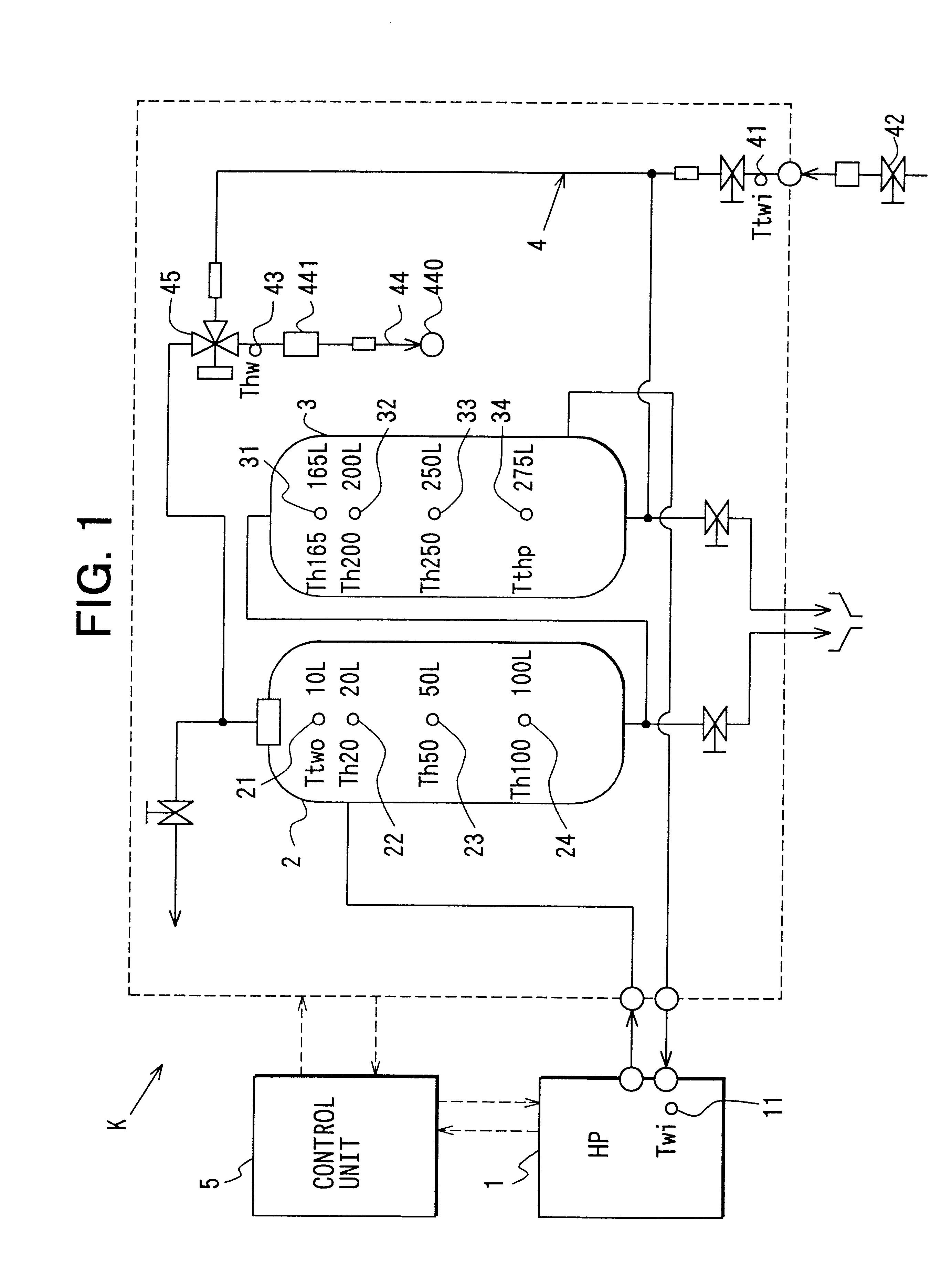
A first preferred embodiment of the present invention will be now described with reference to FIGS. 1-10. As shown in FIG. 1, a hot-water supply system K includes a heat pump unit (HP unit) 1 for heating water by performing water-heating operation (boiling operation). In the heat pump unit 1, refrigerant is compressed by an electrical compressor, and water is heated by using a condensation heat of refrigerant to have a temperature of about 90.degree. C. in maximum. In the first embodiment, carbon dioxide is used as refrigerant, for example.

Double-pipe type tanks 2, 3 are disposed to store hot water heated by the heat pump unit 1. By operation (boiling operation) of about 6 hours of the heat pump unit 1, hot water is fully stored in the tanks 2, 3. In the first embodiment, both the tanks 2, 3 are fully filled with hot water of about 300 liters.

A thermistor 11 is disposed in the heat pump unit 1 at a water supply side to detect a water temperature Twi flowing into the heat pump unit 1...

second embodiment

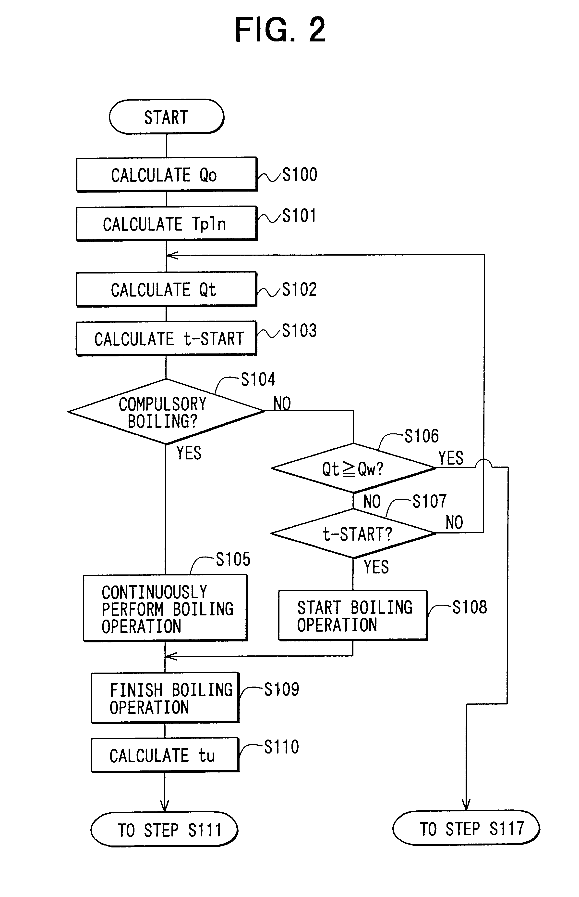
A second embodiment of the present invention will be now described with reference to FIG. 11. In the above-described first embodiment, as shown in FIGS. 7A and 7B, the general-boiling operation is started at the general-boiling start time t-START, and is stopped at the time immediately before the time of 7:00, so that the tanks are fully filled with hot water. However, in the present invention, as shown in FIG, 11, the general-boiling operation can be stopped at a general-boiling stop time t-STOP before the time of 7:00, when the target heat storage amount Qw is ensured in the midnight time zone. Even in this case, heat loss of the stored hot water can be restricted. In the second embodiment, the other parts are similar to those of the above-described first embodiment.

A third preferred embodiment of the present invention will be now described with reference to FIG. 12. In the above-described first embodiment of the present invention, the general-boiling time period tw is set so that...

third embodiment

That is, in the present invention, the general-boiling tome period tw' is calculated based on the following formulas (20) and (21).

Lw=.DELTA.Qw / [(Tp-5-THWA).times.4.18.times.SP] (20)

tw'=(Lw-Lt) / [4.5 kW / (Tp-THWA).times.4.18.times.SP] (21)

wherein, Lw is the necessary boiling amount in the midnight time zone, and SP is a specific gravity.

Accordingly, in the third embodiment of the present invention, the heat loss of the stored hot water can be accurately prevented.


PUM


Abstract

In a control unit of a hot-water supply system, a boiling time period is estimated based on a hot-water amount stored in a tank at a time of 23:00, a boiling start time is adjusted so that boiling operation is finished at a time immediately before 7:00. For example, when the hot water amount stored in the tank is smaller at the time of 23:00, the boiling time period is made longer and the boiling start time is made earlier. On the other hand, when the hot water amount stored in the tank is larger at the time of 23:00, the boiling time period is made shorter and the boiling start time is made later.

Description

This application is related to Japanese Patent Application No. 2000-367052 filed on Dec. 1, 2000, the contents of which are hereby incorporated by reference.1. Field of the InventionThe present invention relates to a hot-water supply system in which water is boiled using electrical power.2. Description of Related ArtIn a conventional hot-water supply system described in JP-B2-2858788 or in JP-B2-63-35904, electrical power is supplied to a heater in a midnight time zone which is cheapest in power rate, so that water is boiled and a hot-water storage tank is filled up in the midnight time zone. Specifically, in the conventional system of JP-B2-2858788, an on-off control of an electrical supply to the heater core is performed at different time zones. On the other hand, in the conventional system of JP-B2-63-35904, the supply of the electrical power to the heater starts from a start time of the midnight time zone.However, in the-above-described conventional systems, because a hot-water ...

Claims


Application Information

Patent Timeline
Patent Type & Authority Patents(United States)
IPC IPC(8): F24D19/00F24D19/10F24H1/18
CPCF24D19/1051F24D19/1054
Inventor NOMURA, SATOSHISAKAKIBARA, HISAYOSHITAKAHASHI, EIJIYOSHIMI, TOMOHISAKOBAYAKAWA, TOMOAKIKUSAKARI, KAZUTOSHISAIKAWA, MICHIYUKI
Owner CENTRAL RESEARCH INSTITUTE OF ELECTRIC POWER INDUSTRY
Why Eureka
Try Eureka