
Printing system, thermal printer, printing control method, and data storage medium

a printing control method and thermal printer technology, applied in printing and other directions, can solve the problems of inability to use thermal printer types, inability to use additive color thermal paper, and limited use of two-color thermal printers

Inactive Publication Date: 2002-09-12
SEIKO EPSON CORP
View PDF0 Cites 14 Cited by
  • Summary
  • Abstract
  • Description
  • Claims
  • Application Information

AI Technical Summary

Benefits of technology

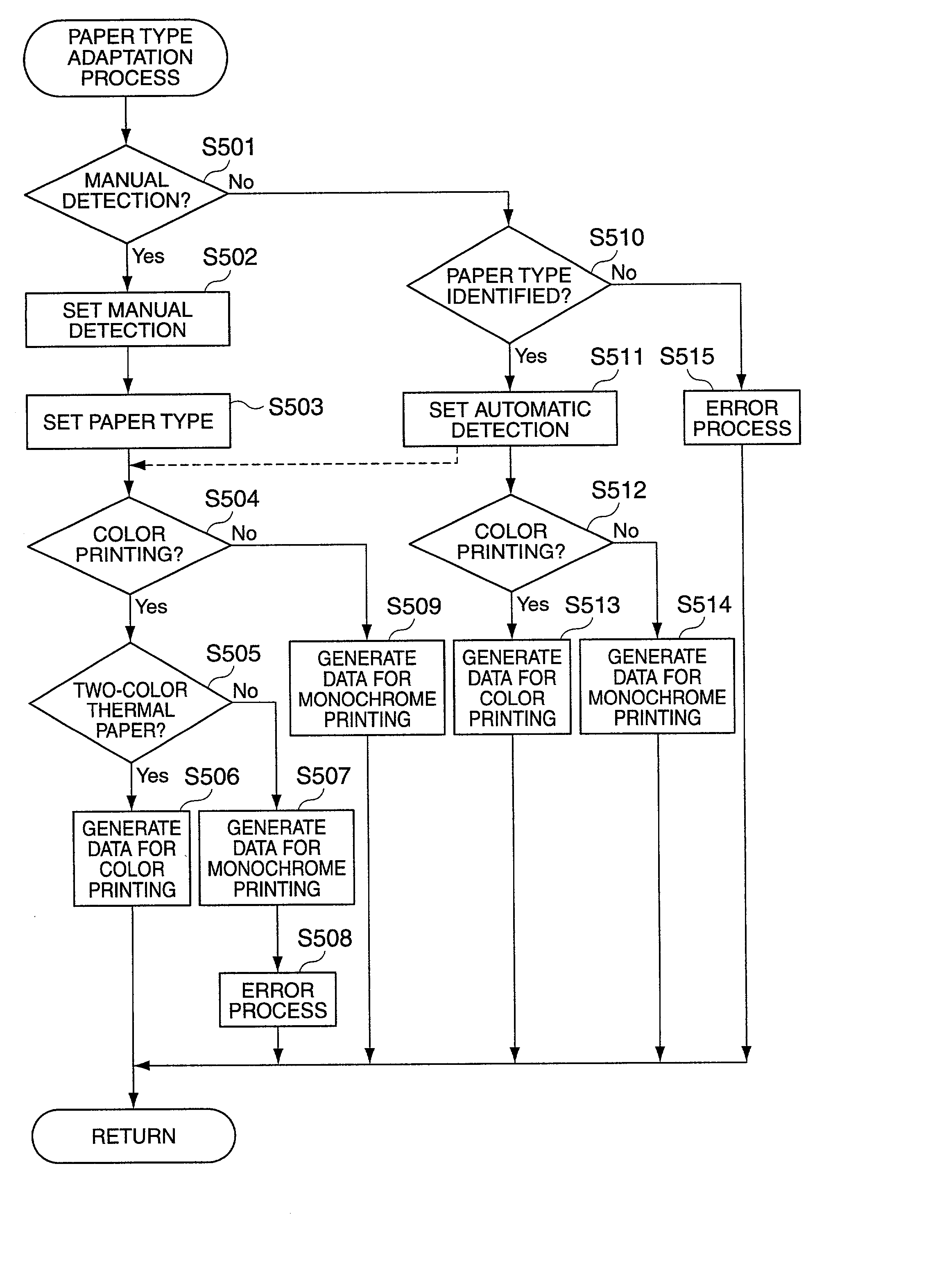
0016] With consideration for this problem an object of the present invention is therefore to provide a printing system, a thermal printer, a printing control method, and a data storage medium able to apply a printing process appropriate to the type of thermal paper loaded when the paper is replaced.

Problems solved by technology

Two-color thermal printers have conventionally been limited to printing with either additive color thermal paper or subtractive color thermal paper.
For example, if a thermal printer that uses subtractive color thermal paper becomes the market leader, thermal paper supplies become dominated by subtractive color thermal paper while additive color thermal paper becomes less common and not as readily available.
Users of thermal printers that cannot use the type of thermal paper that is most readily available are thus inconvenienced by the need to look for the necessary type of thermal paper because supplies of that type have been reduced.
A drop in the supply of that particular type of thermal paper also increases the cost of that particular type, making the paper more expensive for the user.
Thermal printers that cannot use the type of thermal paper that is most commonly available are thus extremely inconvenient printers to use.

Method used


Image

  • Printing system, thermal printer, printing control method, and data storage medium
  • Printing system, thermal printer, printing control method, and data storage medium
  • Printing system, thermal printer, printing control method, and data storage medium

Examples


Embodiment Construction

[0055] A preferred embodiment of the present invention is described below with reference to the accompanying figures. It will be noted that the following embodiments are shown by way of description only and shall not limit the scope of the invention. It will be obvious to one with ordinary skill in the related art that various alternative embodiments can be achieved by replacing some or all of the elements described below with equivalent elements, and that all such variations are included in the scope of this invention.

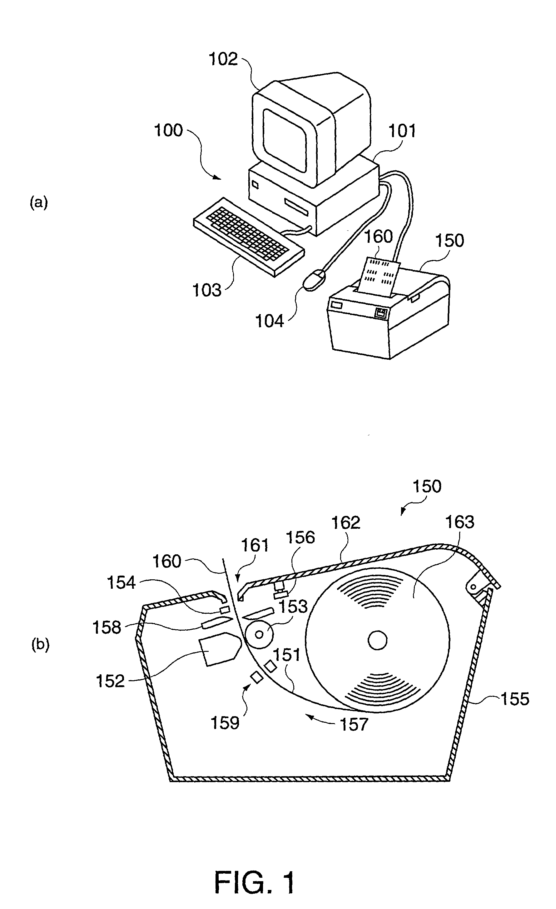
[0056] FIG. 1A is a perspective view of a typical printing system having a printer and a host computer, and FIG. 1B is a sectional view of the printer. A printer and a printer driver functioning to relay print settings for the printer and commands from an application for printing to the printer are described below using by way of example a printing system as shown in FIG. 1A.

[0057] As shown in FIG. 1A this printing system has a host computer 100 and a printer 150 for ...


PUM


Abstract

A printing system, a thermal printer, a printer driver, a printing control method, and a data storage medium control the printing process according to the type of thermal paper that is loaded into the printer when the paper is replaced. By appropriately controlling address selector 1103, a print head controller 811 stores black print pixel data and red print pixel data in first data buffer 1104a for storing low energy level print pixel data or second data buffer 1104b for storing high energy level print pixel data according to the type of thermal paper in use. A logic circuit unit 1105 outputs the current pattern data to the print head 152 based on the low level print pixel data and high level print pixel data.

Description

BACKGROUND OF THE INVENTION[0001] 1. Field of the Invention[0002] The present invention relates to a printing system, a thermal printer, a printing control method, and a data storage medium. More particularly, this invention relates to a printing system, a thermal printer, a printing control method, and a data storage medium that apply a printing process appropriate to the type of thermal paper that is loaded in the printer.[0003] 2. Description of the Related Art[0004] Line thermal printers and other types of thermal printers ("printers" below) have one or more rows of plural independently driven and heated heat elements. Such printers print by selectively driving (heating) the heat elements to heat a particular spot on thermal paper disposed opposite the driven heat element, thereby producing a desired color on the thermal paper. The colors produced in thermal paper used in this type of printer differ according to the amount of heat energy (applied energy) applied by the heat elem...

Claims


Application Information

Patent Timeline
Patent Type & Authority Applications(United States)
IPC IPC(8): B41J2/355B41J2/315
CPCB41J2/355B41J2/315
Inventor MINOWA, MASAHIROIMAI, SATORU
Owner SEIKO EPSON CORP
Learn More