Portable spa

a spa and portability technology, applied in swimming pools, physical therapy, gymnasiums, etc., can solve the problems of affecting the appearance of the deck, affecting the operation of the spa, and being difficult to remove and subsequently install at a different location, so as to achieve convenient access to the equipment for spa operation and not hindered

Inactive Publication Date: 2002-09-19
HORWOOD TIM P +2
View PDF0 Cites 2 Cited by
  • Summary
  • Abstract
  • Description
  • Claims
  • Application Information

AI Technical Summary

Benefits of technology

0011] The present invention provides a spa for use in heating and circulating water in the form of a self-contained unit having all of the equipment necessary for operation of the spa. The spa is capable of either above-ground installation in the manner of a portable spa or direct in-ground installation in the manner of a permanently installed spa. In either case, regardless of the manner of installation, access to the equipment for operation of the spa is convenient and not hindered in any way.

Problems solved by technology

While in-ground spas are generally considered more aesthetically pleasing than portable spas, they are also relative expensive and time consuming to install and are virtually impossible to remove and subsequently install at a different location.
This undesirably adds to the installation expense and requires construction of a deck or the like to cover the gap between the top of the spa and the retaining wall.
This has the disadvantage that it detracts from the appearance of the deck while increasing the expense.
It also may be inconvenient to maintain or repair the spa's equipment, since one must crawl under the deck.
Similar disadvantages arise when a portable spa is installed below ground level.
Not only is the cover for this hole (in the deck between the spa and the retaining wall) usually unattractive, but the hole itself poses a potential safety hazard.

Method used


Image

  • Portable spa
  • Portable spa
  • Portable spa

Examples


Embodiment Construction

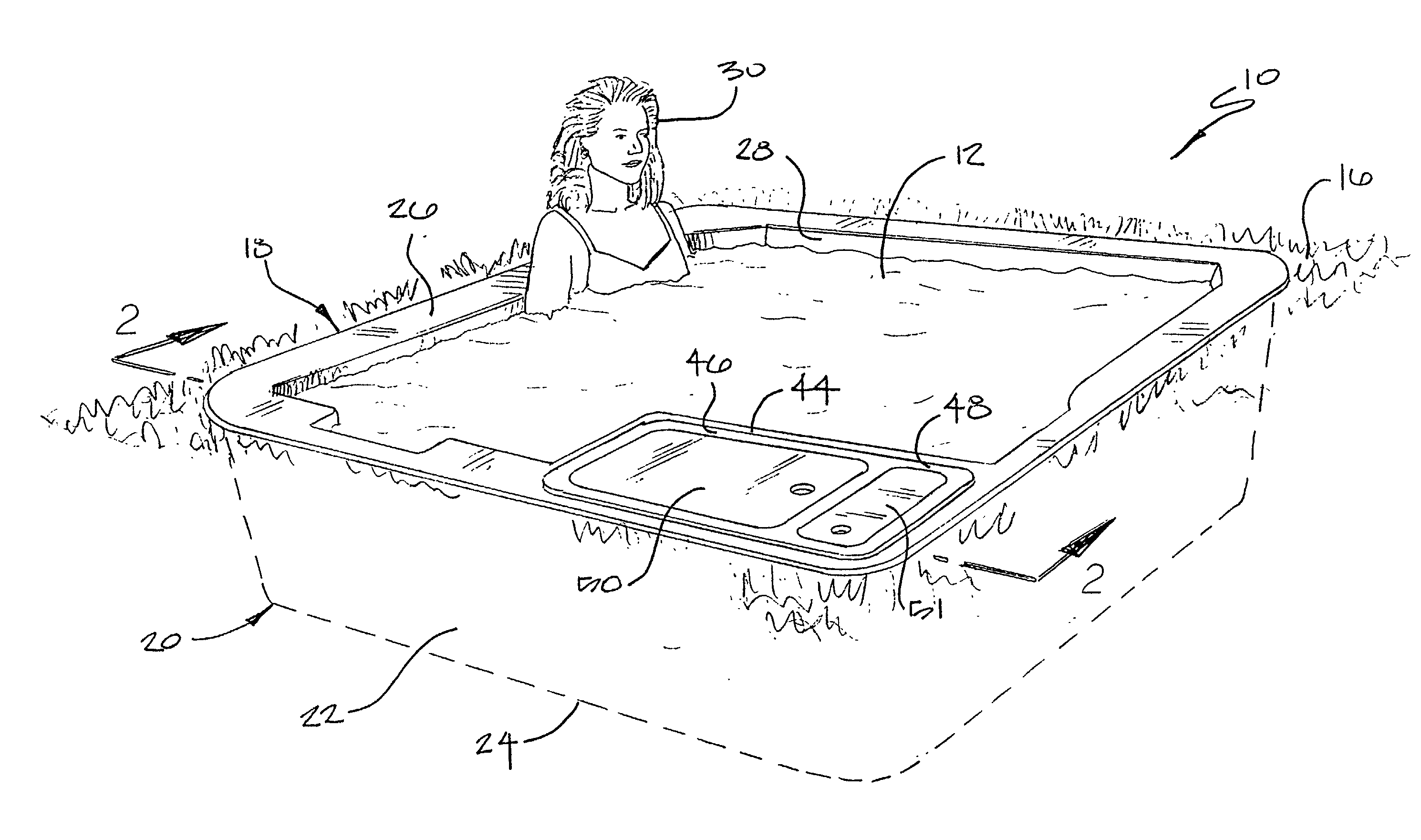
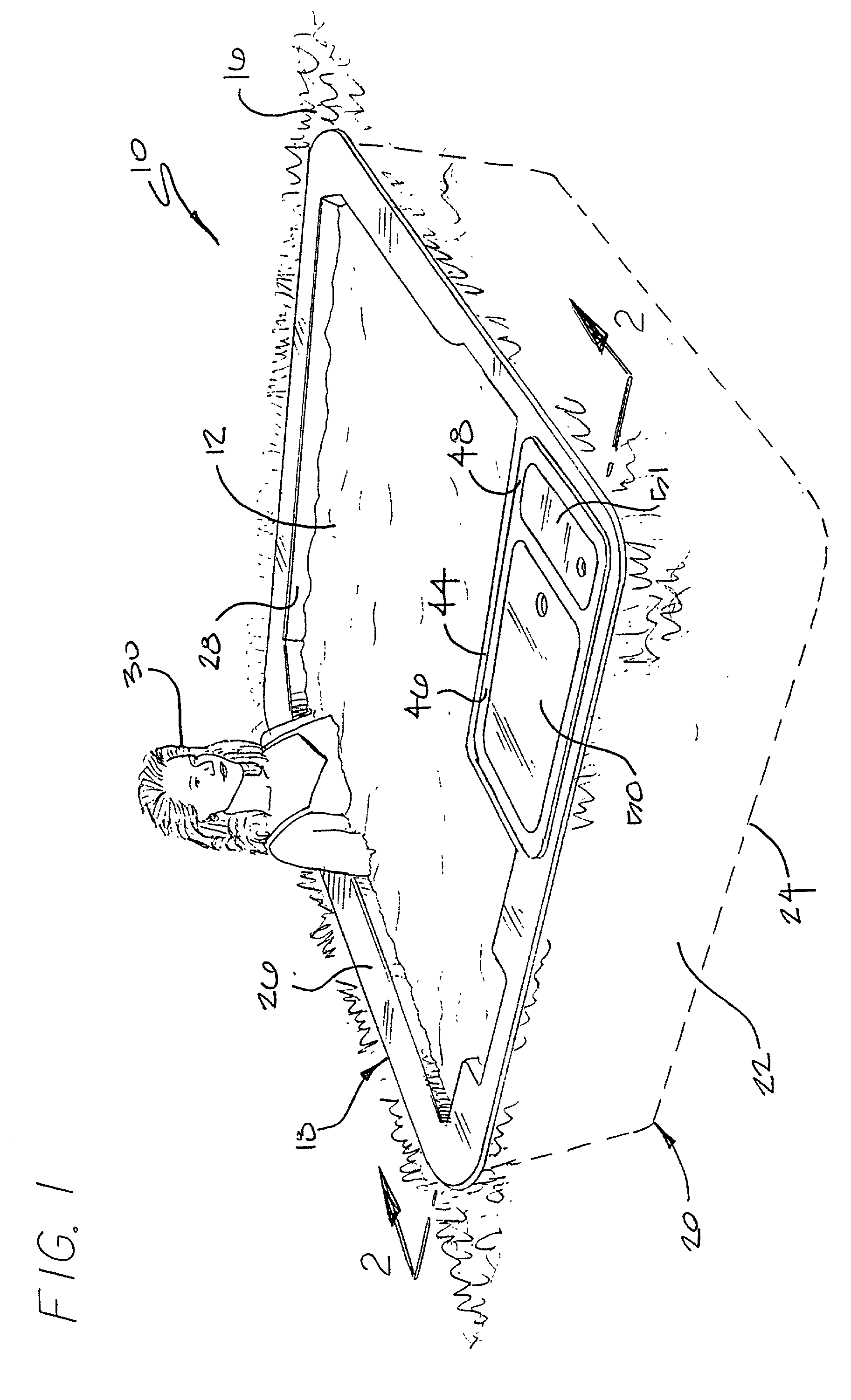
[0027] As shown in the accompanying drawings, the present invention is embodied in a spa, indicated generally by the reference numeral 10, for use in heating and circulating water 12 in the traditional manner. The spa 10 is capable of either above-ground installation, in which a raised deck 14 may be constructed around the spa, or direct in ground installation, in which the spa is installed in the ground 16 with the earth directly in contact with the side of the spa. In either case, access to the equipment required for service of the spa 10 is convenient and not hindered in any way by the manner of installation.

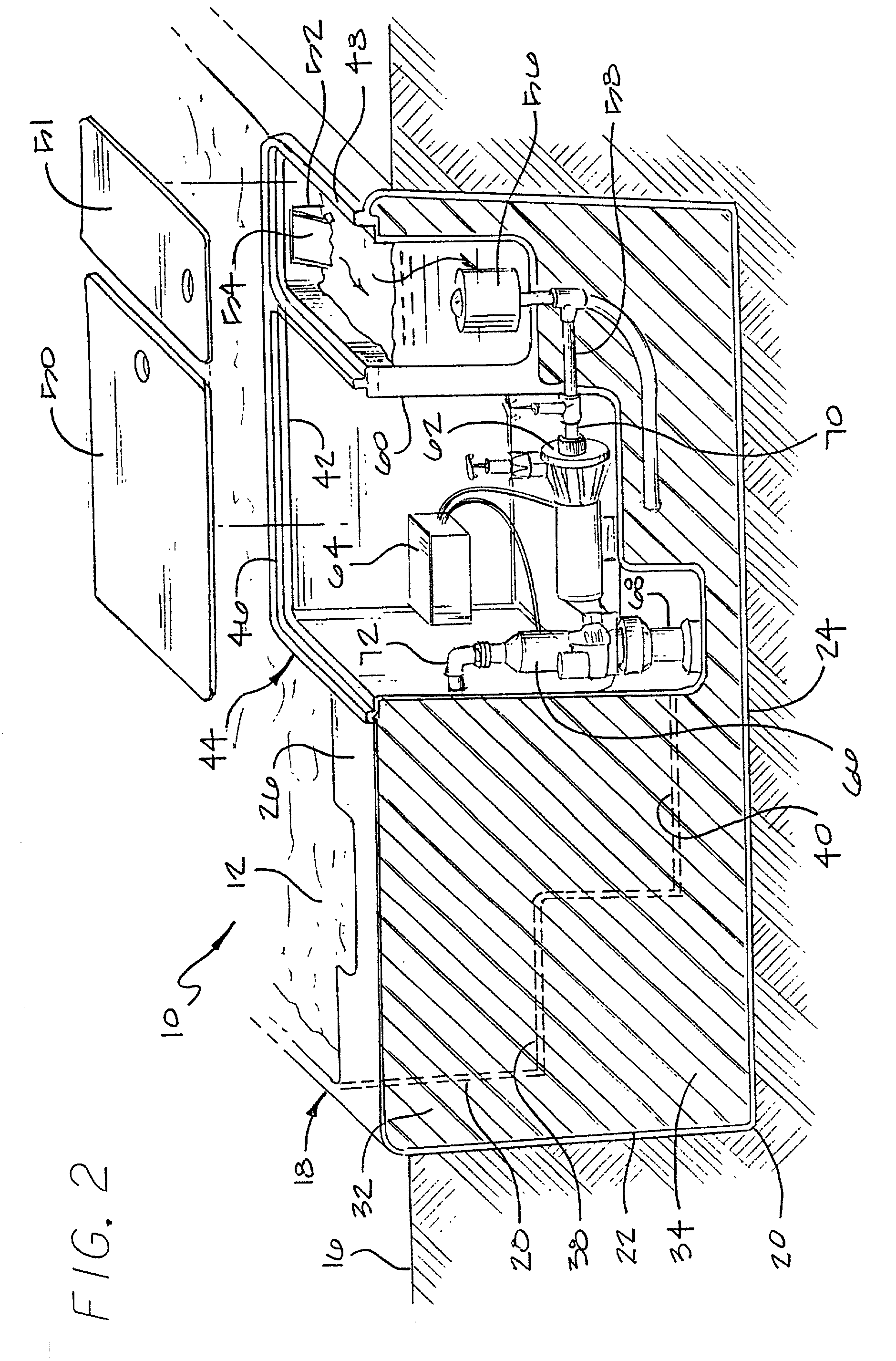
[0028] FIG. 1 shows the spa 10 installed directly in the ground 16. However, whether the spa 10 is installed in the ground 16, as in FIG. 1, or above the ground, as in FIG. 4, the basic structure of the spa is still the same. It is defined by a shell 18, which may be constructed of fiberglass, acrylic, high-impact thermoplastic materials, or any other suitable lightweight, hi...


PUM


Abstract

A portable spa comprises a reservoir for holding water and an outer wall spaced outwardly from the reservoir. The spa includes an equipment bay located between the reservoir and the outer wall that is accessible from an opening at a top portion of the spa. A cover over the opening to the equipment bay is removable from the top portion of the spa to permit access to the equipment bay. The equipment bay contains substantially all of the equipment necessary for operation of the spa and can be conveniently accessed free of any obstructions around the side of the spa. The spa can be installed either above ground in the manner of a portable spa, or it can be installed directly in the ground in the manner of a permanent in-ground spa. Reinforcing means comprising an internal support framework supports the spa against the lateral external forces generated as a result of in-ground installation.

Description

RELATED APPLICATION[0001] This is a continuation of application Ser. No. 09 / 491,361, filed Jan. 26, 2000.BACKGROUND OF THE INVENTION[0002] 1. Field of the Invention[0003] The present invention relates to portable spas and, more particularly, to a spa which may be installed either in the ground or above the ground without hindering access to the technical equipment necessary for operation of the spa.[0004] 2. Description of the Related Art[0005] Traditionally, there have been two distinct types of spas, permanent in-ground spas and portable spas that can be installed either above or below the ground. In-ground spas consist essentially of a shell installed in the ground that includes hydro-jets around its perimeter designed to circulate heated water within the spa. Plumbing to the hydrojets must be installed underground and routed to the spa from a remote maintenance area which houses the necessary technical equipment, such as the pumps, heaters, filters and valves. While in-ground sp...

Claims


Application Information

Patent Timeline
Patent Type & Authority Applications(United States)
IPC IPC(8): A61H33/00E04H4/00
CPCA61H33/0087E04H4/0037E04H2004/0068A61H2033/0041A61H2201/0157A61H33/60
Inventor HORWOOD, TIM P.LOVELL, KEITH W.POPE, JOHN E.
Owner HORWOOD TIM P
Why Eureka
Try Eureka