Vehicle-use surroundings monitoring system

a technology for monitoring systems and vehicles, applied in television systems, pedestrian/occupant safety arrangements, instruments, etc., can solve problems such as false alarms, big accidents, and danger of collision

Inactive Publication Date: 2002-10-10
YAZAKI CORP
View PDF2 Cites 22 Cited by
  • Summary
  • Abstract
  • Description
  • Claims
  • Application Information

AI Technical Summary

Problems solved by technology

For example, when a vehicle (the subject vehicle) traveling on the road, such as a highway, with plural lanes changes the lane and simultaneously another vehicle is traveling in the vicinity in an adjacent lane and is catching up with the subject vehicle from the rear-and-side, if the subject vehicle carries out the change of the lane while not awaring of the existence of another vehicle, a big accident would occur.
Further, when the subject vehicle changes the lane and another vehicle slower than the subject vehicle is traveling obliquely ahead of the subject vehicle on the adjacent lane, there would also be a danger of collidation, which requires secure awareness of another vehicle in the vicinity.
With respect to the above prior art vehicle-use surroundings monitoring systems, however, stationary objects, such as tiles in a tunnel, poles of guard rails, road side-objects like a safety zone a zebra pattern with regular intervals and a similar painted pattern on the road, would be detected as approaching objects, whereby a false alarm would be generated.
And, the above false alarm could be raised by fluctuation of the taken-image cause by rock-and-roll of the vehicle.

Method used


Image

  • Vehicle-use surroundings monitoring system
  • Vehicle-use surroundings monitoring system
  • Vehicle-use surroundings monitoring system

Examples


Embodiment Construction

)

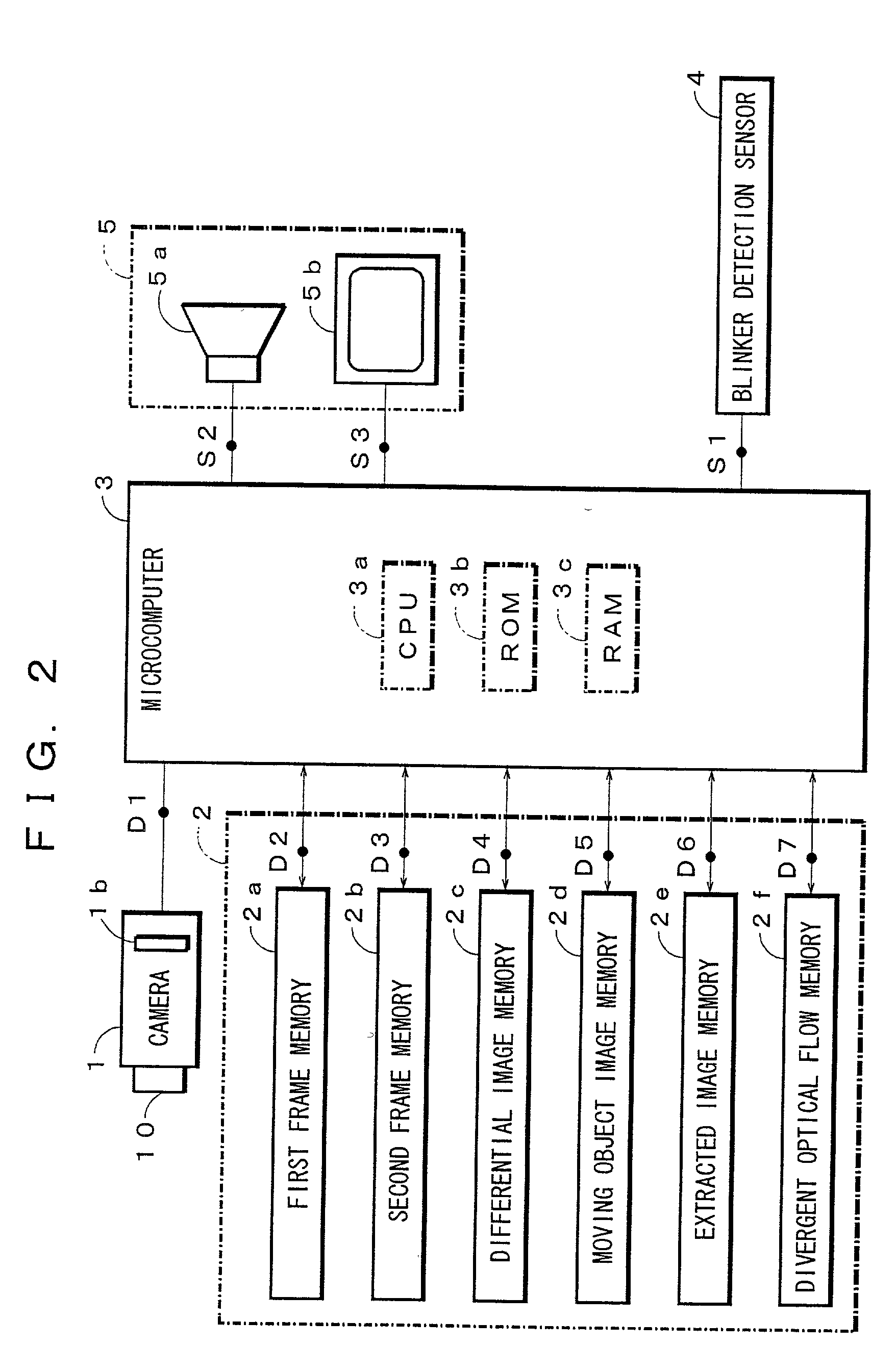
[0046] Embodiment(s) of the present invention will now be described in further detail with reference to the accompanying drawings. FIG. 2 is a block diagram showing an embodiment of the inventive vehicle-use surroundings monitoring system. A camera 1 as an onboard image-taking means image-forms an image of an angle of view decided with a lens 1a. And, the camera 1 is installed at a position from which the rear-and-side of the vehicle is a monitoring area.

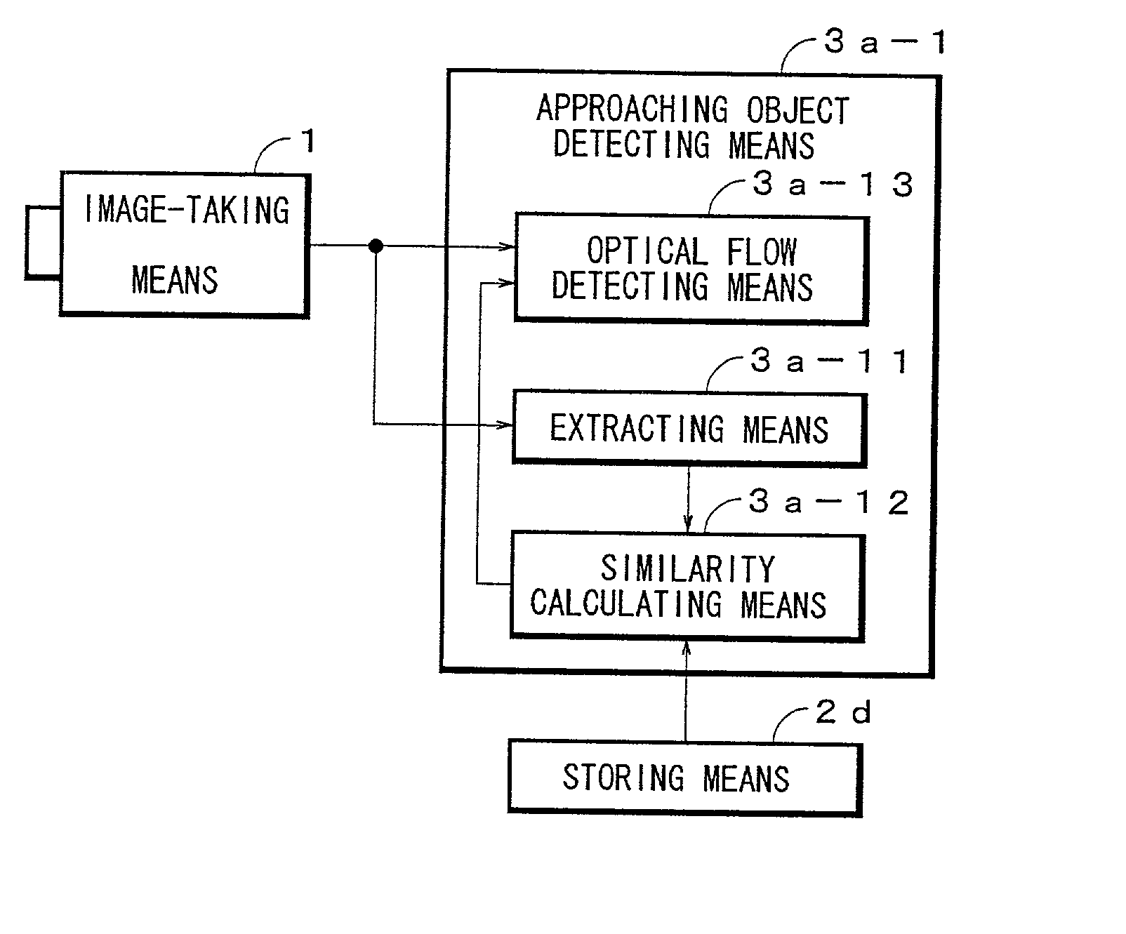
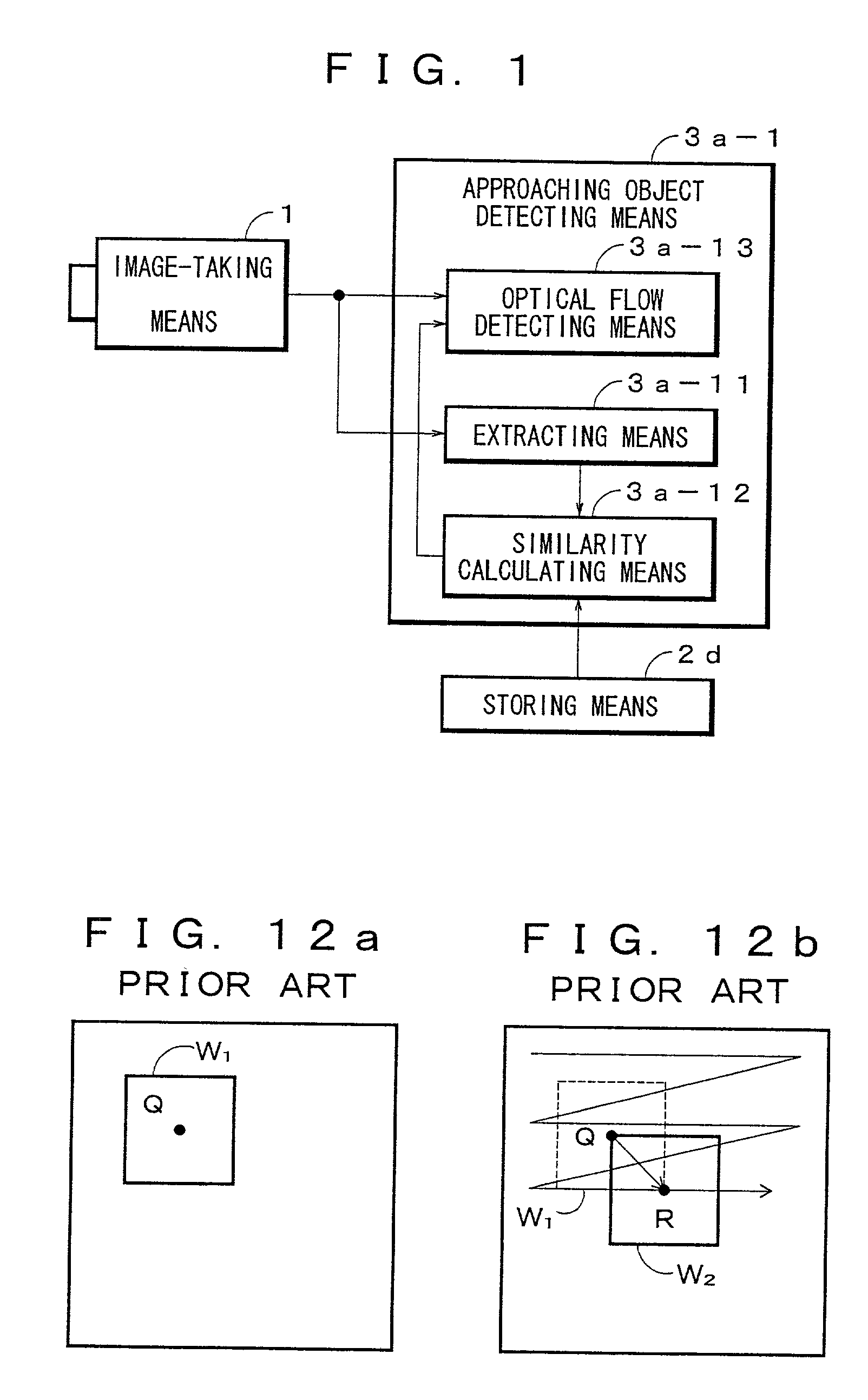
[0047] A memory portion 2 has a first frame memory 2a, a second frame memory 2b, a differential image memory 2c, a moving object image memory 2d as a storing means, an extracted image memory 2e, and a divergent optical flow memory 2f. The first frame memory 2a and the second frame memory 2b temporarily store, as taken-image pixels D2,D3 respectively, a taken-image D1 formed on an image plane 1b of the camera 1 after converting it into pixels of m rows and n columns, for example 512*512 pixels with the luminance of 0-255 gradation, ...


PUM


Abstract

A vehicle-use surroundings monitoring system which prevents a stationary object from being detected as an approaching object thereby to improve a detection accuracy of the approaching object. An onboard image-taking means 1 image-takes the surroundings of a vehicle to obtain a taken-image. An approaching object detecting means 3a-1 detects a real approaching object except a stationary object to be mis-detected as an approaching object by making use of the same point (corresponding points) in two images taken by an image-taking means with an interval of a specified time.

Description

[0001] 1. Field of the invention[0002] The present invention relates generally to a vehicle-use surroundings monitoring system and more particularly to a vehicle-use surroundings monitoring system which monitors the surroundings of a vehicle for giving alarm to a driver by detecting another vehicle approaching from the surroundings of the subject traveling vehicle by using an image obtained by image-taking the road around the subject vehicle by means of an image-taking means such as a camera installed on the subject vehicle.[0003] 2. Description of the Related Art[0004] For example, when a vehicle (the subject vehicle) traveling on the road, such as a highway, with plural lanes changes the lane and simultaneously another vehicle is traveling in the vicinity in an adjacent lane and is catching up with the subject vehicle from the rear-and-side, if the subject vehicle carries out the change of the lane while not awaring of the existence of another vehicle, a big accident would occur.[...

Claims


Application Information

Patent Timeline
Patent Type & Authority Applications(United States)
IPC IPC(8): B60R1/00B60R21/00G06T7/00G06T7/20G06T7/60H04N7/18
CPCB60R1/00B60R2300/804B60R2300/30
Inventor ISHIKAWA, NAOTOOGURA, HIROYUKI
Owner YAZAKI CORP
Why Eureka
Try Eureka