Hydraulic drive system

a technology of hydraulic drive and drive shaft, which is applied in the direction of fluid couplings, servomotors, chairs, etc., can solve the problems of unsatisfactory user experience, jerking start and stop actuation, and more complex and expensive than may be desired to fulfill the function,

Inactive Publication Date: 2002-10-17
A-DEC
View PDF3 Cites 17 Cited by
  • Summary
  • Abstract
  • Description
  • Claims
  • Application Information

AI Technical Summary

Benefits of technology

0005] An object of the present disclosure is to provide a novel, efficient, and economically produced hydraulic drive system.

Problems solved by technology

Some prior systems use drive pumps, motor units, and control circuits which produce movement of the item to be driven in a manner which is not as smooth as may be desired.
In a hydraulically actuated chair, for example, prior systems may produce movement which is too fast, too slow, or may produce jerking start and stop actuation which is uncomfortable for the user.
Prior systems also have been constructed in such a manner that they are more complex and expensive than may be desired to fulfill their functions.
Often prior systems have been produced in such a manner that they require an undesirable number of actuating valves and are produced in a generally open architecture of hoses and connections which are subject to breakage and leakage.

Method used


Image

  • Hydraulic drive system
  • Hydraulic drive system
  • Hydraulic drive system

Examples


Embodiment Construction

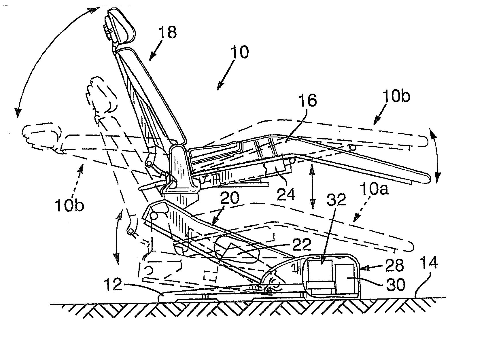
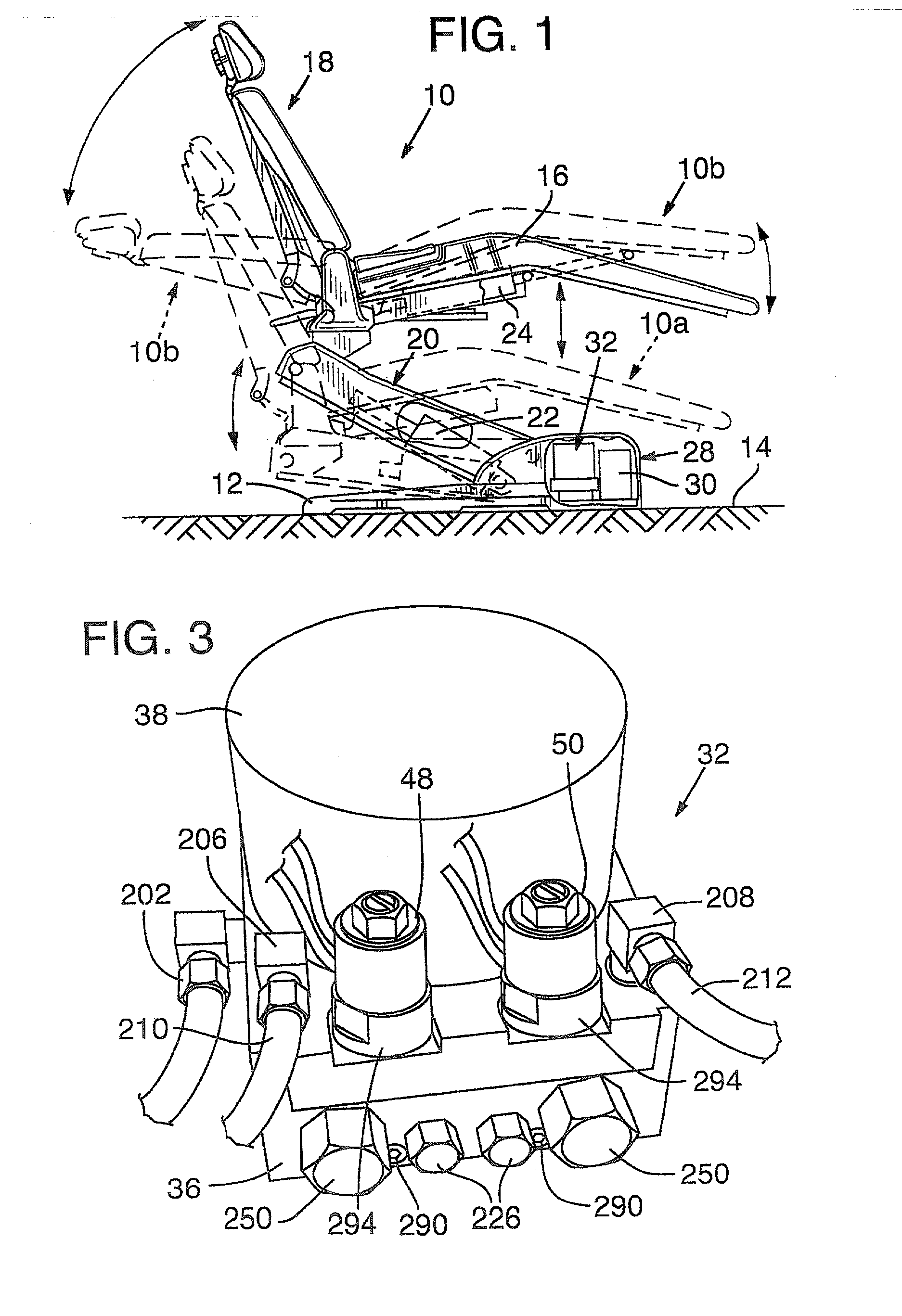
[0037] Referring first to FIG. 1, one manner of use of a hydraulic drive system according to the invention is illustrated for use with a dental chair 10. The chair has a base 12 adapted to rest on a floor 14 with an upper structure including a seat portion 16 and a back, or back rest, 18. The seat is mounted on a lift mechanism 20 which includes an extensible contractible ram, or cylinder, 22. Extension of the ram acts to raise the chair to the elevated position illustrated in solid outline in FIG. 1. Contraction of the ram lowers the chair to the position illustrated in dashed outline at 10a in FIG. 1.

[0038] The chair back 18 is pivotally connected to the rear end of seat 16 and tilting mechanism including a tilt ram, or cylinder, 24 is operable to tilt the seat and back between a generally upright position illustrated in solid outline in FIG. 1 and a rearwardly tilted position illustrated at 10b in dashed outline.

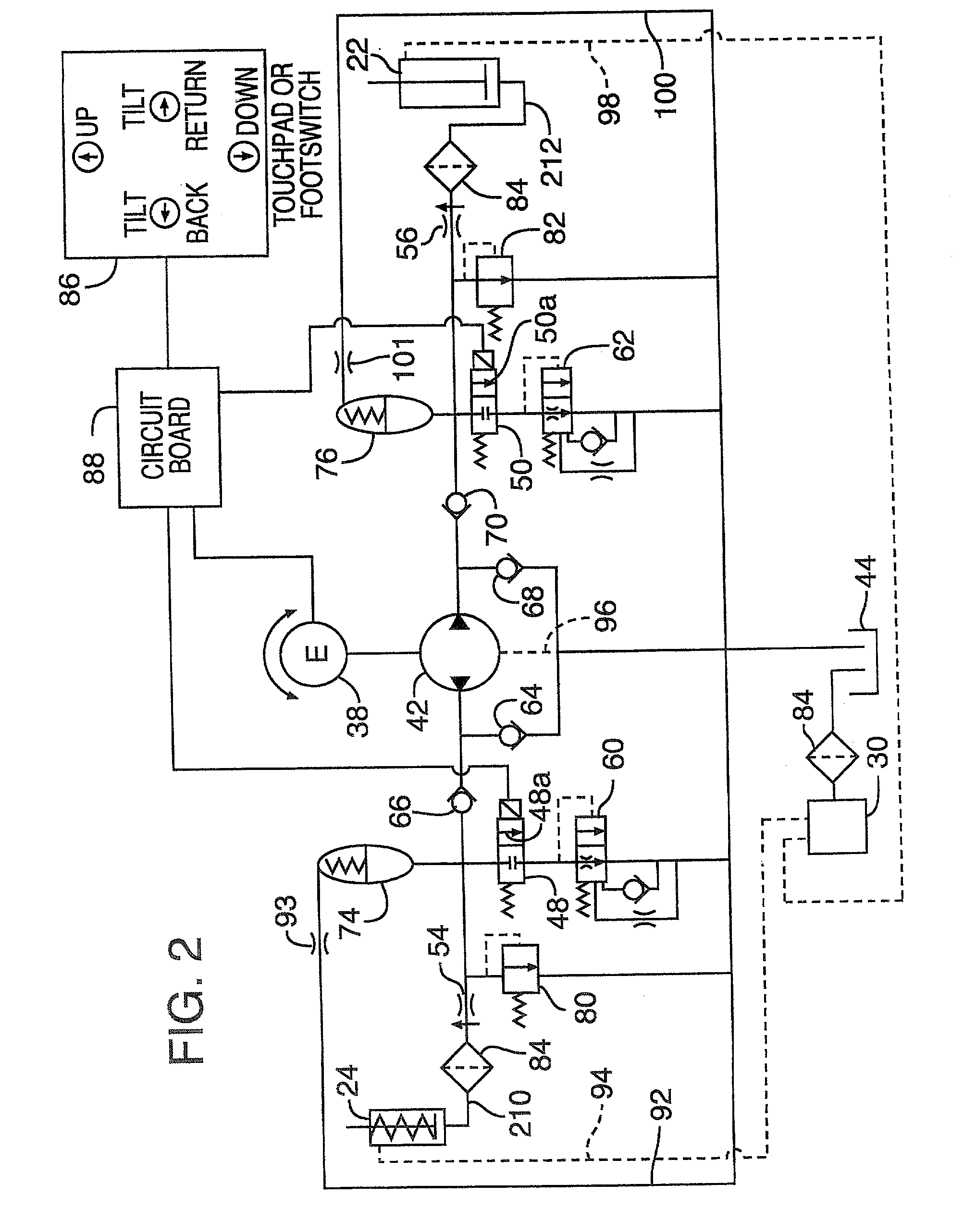
[0039] A hydraulic drive system for the lift and tilt cylinders is i...


PUM


Abstract

A hydraulic drive and fluid control system for a mechanism having at least two fluid actuated cylinder includes a bi-directional motor/gear pump. A monolithic block manifold has intersecting bores formed therein in which valving and control mechanism for the fluid circuit is mounted. The fluid control system includes a variety of elements for providing smooth action of the cylinders at start, stop, and intermediate operations. These include piston-style accumulators, self-actuating fluid flow rate control valves and cushion valves.

Description

This application claims the benefit of U.S. Provisional Patent Application No. 60 / 283,653, filed Apr. 12, 2001.[0001] This invention relates generally to a hydraulic drive system and elements thereof which may be used for actuating devices having multiple operations, such as a chair having both lift and tilt features.[0002] Hydraulic drive systems are used in many operations for powering multiple actions. Examples of such are power actuated chairs, such as dental chairs, which often are operated by pressurized hydraulic fluid systems in which one hydraulic cylinder, or ram, is operable to raise the chair, and a second hydraulic cylinder, or ram, is operable to tilt the chair or a portion thereof. Many prior hydraulic drive systems have been disclosed in the past, but each has had disadvantages.[0003] Some prior systems use drive pumps, motor units, and control circuits which produce movement of the item to be driven in a manner which is not as smooth as may be desired. In a hydrauli...

Claims


Application Information

Patent Timeline
Patent Type & Authority Applications(United States)
IPC IPC(8): A61G15/02A61G15/04A61G15/06F15B7/00A47C3/30F15B7/02F15B11/00F15B11/04F15B11/048F15B11/16
CPCA61G15/02F15B2211/853F15B7/02F15B11/048F15B11/16F15B2211/20515F15B2211/20561F15B2211/27F15B2211/30525F15B2211/31558F15B2211/327F15B2211/40507F15B2211/40515F15B2211/41527F15B2211/41581F15B2211/428F15B2211/46F15B2211/613F15B2211/615F15B2211/625F15B2211/7052F15B2211/71F15B2211/851F15B7/006
Inventor JACKSON, HENRY WARN
Owner A-DEC
Why Eureka
Try Eureka