Actuator, in particular for valves, relays or similar

a technology of actuators and relays, applied in the field of actuators, can solve problems such as energy loss and heating of actuators

Inactive Publication Date: 2002-10-17
ROBERT BOSCH GMBH
View PDF6 Cites 32 Cited by
  • Summary
  • Abstract
  • Description
  • Claims
  • Application Information

AI Technical Summary

Problems solved by technology

The result is energy loss and a heating of the actuator and the supply lines to the switch transistors for controlling the magnet coil.

Method used


Image

  • Actuator, in particular for valves, relays or similar
  • Actuator, in particular for valves, relays or similar
  • Actuator, in particular for valves, relays or similar

Examples


Embodiment Construction

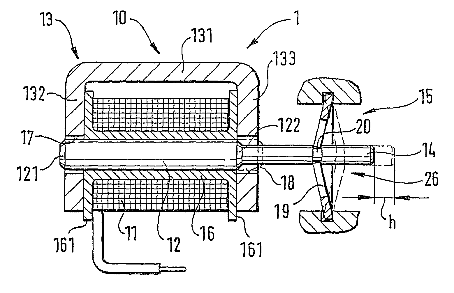
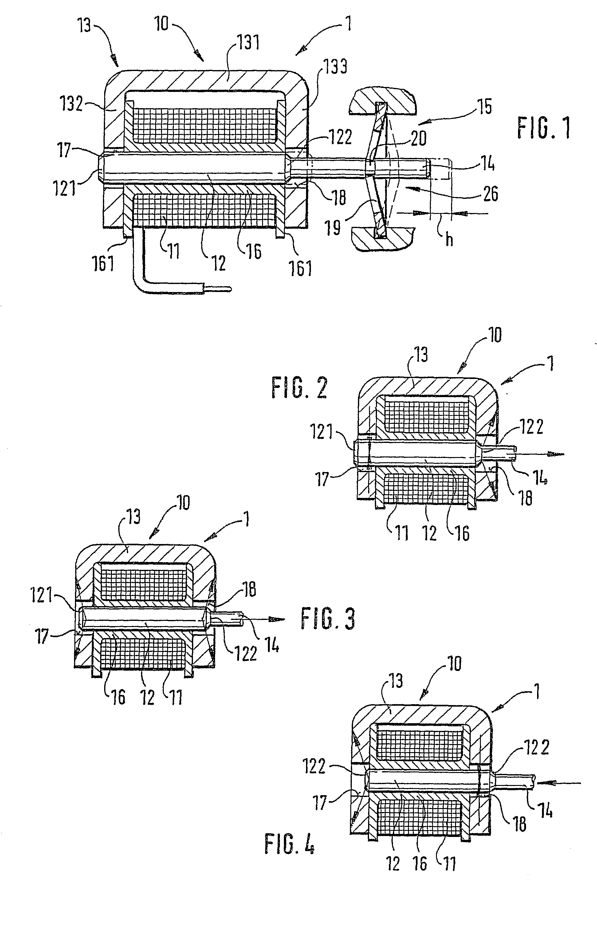
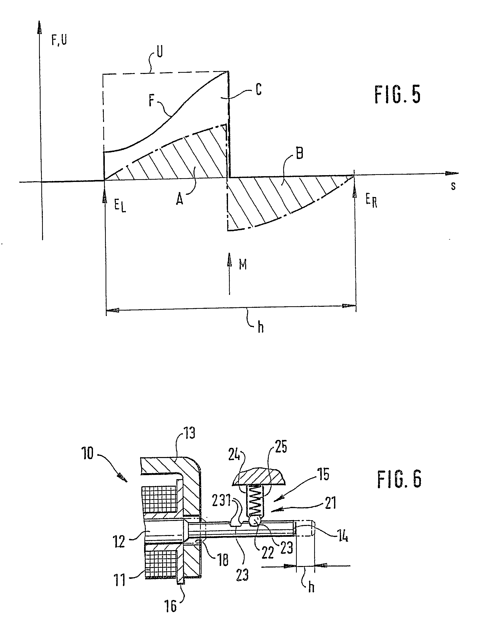
[0017] The electromagnetic actuator 1 for pneumatic or hydraulic intermediary valves or for bistable relays, which is shown in a schematic longitudinal section in FIG. 1, has an electromagnet 10 with a magnet coil 11, with a magnet armature 12 that can be slid between two end positions and with a magnet yoke 13 that constitutes the back iron, as well as an actuation tappet 14 affixed to the magnet armature 12, and a bistable mechanical locking device 15, which comes into play in the end positions of the magnet armature 12, acts on the actuating tappet 14, and fixes the actuating tappet 14 with the magnet armature 12 in each of its two end positions.

[0018] The magnet coil 11 is wound on a hollow cylindrical coil body 16 similar to a yarn spool, which is bounded on the ends by two annular flanges 161. The magnet yoke 13 is U-shaped and has two yoke legs 132, 133, which extend parallel to each other and are connected to each other by means of a yoke bridge 131. The magnet yoke 13 embra...


PUM

PropertyMeasurementUnit
lengthaaaaaaaaaa
widthaaaaaaaaaa
drive-forceaaaaaaaaaa

Abstract

An actuator, in particular for valves, relays, or the like, is disclosed, which has an electromagnet (10) with a magnet coil (11), a magnet armature (12) that can be slid between two end positions, and a magnet yoke (13), and has an actuation tappet (14) driven by the magnet armature (12). In order to produce a bistable actuator with a low power consumption and a low heating of current-carrying components-particularly when long switching times in both switch positions are required, on the one hand, the electromagnet (10) is embodied so that its magnet armature (12) has a stable middle position that is disposed between its two end positions, which are determined by the two switch positions of the actuator, and that can be approached from both end positions by supplying current to the magnet coil (11), and on the other hand, a bistable mechanical locking mechanism (15) is provided, which acts on the magnet armature (12) or on the actuation tappet (14) and comes into play in the end positions of the magnet armature (12) (FIG. 1).

Description

PRIOR ART[0001] The invention is based on an actuator, in particular for valves, relays, or the like, as generically defined by the preamble to claim 1.[0002] Electromagnetic actuators are generally embodied in a monostable manner, i.e. the magnet armature of the actuator--when not supplied with energy--has a stable, definite end position, the so-called neutral position. This end position is usually set by the spring force of a restoring spring, whereas the transfer into its other end position, the so-called switched position, is achieved by supplying power to the magnet coil or the excitation winding of the electromagnet of the magnet armature. In order to hold the magnet armature in the switched position, the magnet coil must be continuously supplied with current, without producing mechanical work in so doing. The result is energy loss and a heating of the actuator and the supply lines to the switch transistors for controlling the magnet coil.ADVANTAGES OF THE INVENTION[0003] The ...

Claims


Application Information

Patent Timeline
Patent Type & Authority Applications(United States)
IPC IPC(8): H01F7/124H01F7/16H01H51/08
CPCH01F7/124H01H51/08H01F7/1607
Inventor KRIMMER, ERWINSCHULZ, WOLFGANGBRENDLE, MATTHIAS
Owner ROBERT BOSCH GMBH
Why Eureka
Try Eureka