Sanitary design gear pump

a gear pump and sanitary technology, applied in the direction of rotary/oscillating piston pump components, machines/engines, liquid fuel engines, etc., can solve the problems of high cost of pumps, and high cost of sanitary pumps, so as to reduce the risk of damage, and reduce the cost of pump replacement.

Inactive Publication Date: 2002-10-31
ODEN MACHINERY +1
View PDF0 Cites 23 Cited by
  • Summary
  • Abstract
  • Description
  • Claims
  • Application Information

AI Technical Summary

Benefits of technology

[0022] It is the primary object of the present invention to overcome the numerous disadvantages and limitations, as set forth above, of the presently known sanitary rotary positive displacement pumps, and to set forth the unique and novel specifications for a sanitary gear pump.

Problems solved by technology

In either case, these pumps are very expensive by virtue of their complexity and extensive and robust construction requirements.
This pump type is very expensive because of the complex shape of the rotor, the close tolerances, robust construction and the expensive materials utilized in its construction.
These sanitary pumps are, like the other common types, very expensive by virtue of their complex structures, expensive materials of construction and robust design requirements.
This may be generally the case because available industrial service (non-sanitary) gear pumps are not designs which are acceptable or easily adaptable for sanitary service.
Even though sanitary versions of gear pumps are not generally known in commercial practice, it is nevertheless true that industrial service gear pumps are often used in sanitary applications even though such pumps do not meet generally accepted sanitary standards or regulatory statutes and requirements.
It is also generally understood that where low or very low flow rates are required, sanitary positive displacement designs are generally commercially unavailable.
It is also to be noted that among knowledgeable and experienced designers of sanitary devices, equipment and pumps there has long been held the general opinion that the external gear type pump is unsuitable for sanitary service and applications because the bearings which support each gear shaft are usually internal to the pump and in contact with the liquid being pumped.
However, removal of the pumping gears requires the use of tools.
The pump is thus particularly designed as a clean-in-place device and is not suited for easy or rapid disassembly for cleaning or inspection.
However, it does not present a complete solution or one that is in compliance as a sanitary pump to the specifications of and design requirements of the 3-A Sanitary Standards Symbol Administrative Council (US) Standard Number 02-09 "Standards for Centrifugal and Positive Rotary Pumps for Milk and Milk Products."

Method used


Image

  • Sanitary design gear pump
  • Sanitary design gear pump
  • Sanitary design gear pump

Examples


Embodiment Construction

. 10-23

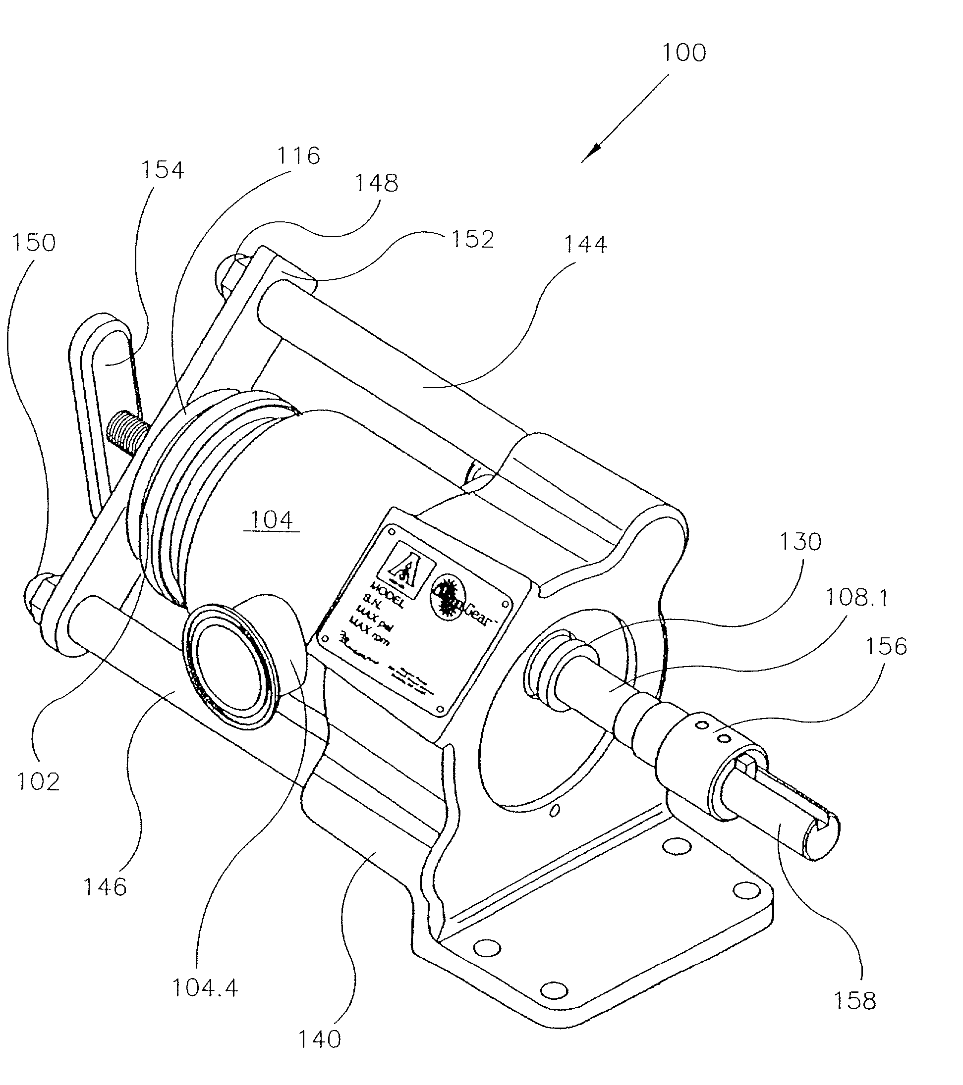
[0102] The present invention consists of a unique and novel sanitary design gear pump providing solutions to the problems associated with using gear pumps in sanitary applications.

[0103] The present invention provides a sanitary gear pump which is low in cost, simple and robust in construction, contains few parts, is readily disassembled for cleaning and inspection without the use of tools, has a very wide operating temperature range, has a simple and versatile shaft seal arrangement, provides for multiple mount orientations, can be mounted and dismounted without loss of drive alignment, and allows dismount, tear down, re-assembly and re-mount with the use of only one hand operated screw fastener. All of these features are unique and novel in their embodiment, and are fully illustrated and described in detail herein.

[0104] As can best be seen from FIGS. 10, 12, 13 and 17, the preferred embodiment consists generally of a sanitary gear pump indicated generally at 100. It is com...


PUM

PropertyMeasurementUnit
temperatureaaaaaaaaaa
viscosityaaaaaaaaaa
temperatureaaaaaaaaaa

Abstract

A sanitary design gear pump in which two gear shaft bearing blocks constitute hand removable structural end bodies of the pump. The gear shaft bearing journals extend completely through the blocks for easy cleaning and are sealed by O-rings retained by simple clamp plates. Gear cavity bore extends only the length of the largest gears, among interchangeable gear sizes. Bearing block to gear cavity seals are located at the ends of the gear bore to eliminate entrapment zones, minimal intrusion of the bearing blocks into the gear cavity allowing a large pump operating temperature range. Shaft seals of many different types can be contained in a simple hand removable cartridge. Complete pump disassembly is by one manually operated tee-handled clamp fastener. The drive and driven gear shafts are of different diameters to aid and assure correct assembly. The assembled pump slides into a pump mount with integral tie rods sealing the pump and securing it to the mount. The mount foot is reverse of the body, allowing the pump ports orientation to be selected at 90° intervals by a pin and groove engagement of the pump body and mount. The pump mount allows repeated pump removal without loss of pump-drive alignment. The drive gear shaft is splined to allow free pump removal from its mount and drive to pump disassembly without need to remove a shaft coupling. Pump displacement can be altered, requiring only interchange of gears and the drive end bearing block. The pump design meets the requirements of the 3-A Sanitary Standard 02-09 as promulgated by the 3-A Sanitary Standards Symbol Administrative Council.

Description

[0001] The present invention relates generally to gear pumps, and more particularly to a sanitary design gear pump in which two gear shaft bearing blocks constitute hand removable structural end bodies of the pump.[0002] Among the many types of known rotary positive displacement pumps, gear pumps constitute an old and well developed patent and commercial art. Gear pumps are most frequently found in the patent art and commercial practice as liquid transfer devices and as pressure pumps for hydraulic systems. They are well characterized as to their relative pumping virtues as well as their limitations in application and use. Gear pumps are also employed and well understood as metering pumps and more recently as dosing, dispensing or liquid filling pumps. For example, Oden Corporation of Buffalo, N.Y., USA manufactures a liquid filling machine product known as SERVO / FILL.sup.e which now uses the gear pump of the present invention coupled to a servo controlled motor to define a liquid d...

Claims


Application Information

Patent Timeline
Patent Type & Authority Applications(United States)
IPC IPC(8): F04C2/08F04C2/18F04C13/00
CPCF04C2/086F04C2/18F05C2225/04F04C13/005F04C13/001
Inventor PHALLEN, IVER J.JEZUIT, RICHARD J. JR.MESSING, DAVID C.TUFTE, GREGORY N.AMYOTTE, FRANK L.MAKI, BRUCE A.
Owner ODEN MACHINERY
Why Eureka
Try Eureka