Linear peristaltic pump

a peristaltic pump and peristaltic technology, applied in the direction of pump parameters, motor parameters, pump control, etc., can solve the problems of short tubing life, unstable and decreasing flow characteristics of the pump, and short tubing life, so as to prolong increase the flow range, and increase the useful pump tube life.

Inactive Publication Date: 2001-04-10
NIAGARA PUMP CORP
View PDF80 Cites 280 Cited by
  • Summary
  • Abstract
  • Description
  • Claims
  • Application Information

AI Technical Summary

Benefits of technology

It is a further object of the present invention to provide a linear peristaltic pumping apparatus for pumping liquids which includes a high durometer compressible elastomeric liquid flow tube, an infeed valve assembly, an outfeed valve assembly, an extensible and retractable actuator anvil having a round surface which engages the flow tube at all times, an opposed anvil having a round surface in engagement with the flow tube at all times, the flow tube being held between the anvils in a slightly compressed state when the actuator anvil is retracted, and control means for causing the movable anvil to be sequentially extended and retracted to cause flow within the flow tube from the infeed valve assembly to the outfeed valve assembly. With this apparatus the lumen of the flow tube to the sides of the anvils is not completely reduced to zero volume during displacement compression whereby gas embolisms do not erupt or explode when discharged.
In summary, the in-line or linear three element electronically controlled peristaltic pump of this invention is provided with linear actuators, typically pneumatic, each actuator capable of driving dual symmetrical pump tube compression anvils which compress a high durometer reinforced multi-layer flow tube from each side such that a higher liquid pumping pressure can be produced than the pneumatic pressure applied to the actuators. The high durometer flow tube allows priming and pumping of liquids at viscosities and pressures not previously possible with a linear peristaltic pump. The dual symmetrical anvil arrangement greatly extends useful pump tube life. Additional displacement actuators may be added in modules to incre

Problems solved by technology

Rotary peristaltic pumps, in which compressive elements, generally rollers, fully occlude a flexible tube as them move in a circumferential, circular arc over tubing which is supported by a circular backstop, are known to offer very limited tubing life and generally are capable of pumping only low viscosity liquids at very low discharge pressures and at very modest flow rates.
This fundamental design characteristic further contributes to short tubing life and to unstable and decreasing flow characteristics of the pump over useful tubing life.
However, these pumps are relatively large, expensive, and are controllable only in terms of their flow rate which is a function of the rotations per minute at which the pump is driven, and they are not usually suitable for sanitary applications such as pharmaceutical manufacturing or food processing.
Although the general form of the three element linear peristaltic pump has been widely applied in the prior art, many limitations and shortcomings of these designs are evident.
1. Inability of prior designs to pump liquids at comparatively high pressures. Nearly all of the previous designs utilize a small scale and method of construction unsuited to provide the power needed for high pressure pumping. The liquid flow tubes are generally soft comparatively flexible material unable to contain high differential pressures and they are not typically contained to prevent pressure distortion or rupture. The compressive elements are most typically of a geometry unsuited to high force application to the tube wall in order to create the high pressure pinch valving required of a high pressure pump. Where high pressure linear peristaltic designs have been attempted, they have utilized hydraulic actuation, requiring expensive pump construction and limiting utility because of the requirement for a high capacity and pressure hydraulic supply.
2. Inability of prior designs to pump high viscosity liquids. Pumping high viscosity liquids will generate high pump discharge pressures. The inability of known types to pump at high pressures has previously been discussed. In addition, to pump high viscosity liquids a competent and useful pump must be capable, by its own action, of priming such liquids into the pump at start-up and during continuous running. The devices of the prior art are not generally suited to this in that the rebound capability of the liquid flow tube is extremely inadequate to such service. Further, there are usually no provisions or ability to allow independent control and adjustment of the priming function within the pump cycle, and the compression anvils which are in contact with the tubing are not geometrically suited to the high force operation required for such se

Method used


Image

  • Linear peristaltic pump
  • Linear peristaltic pump
  • Linear peristaltic pump

Examples


first embodiment

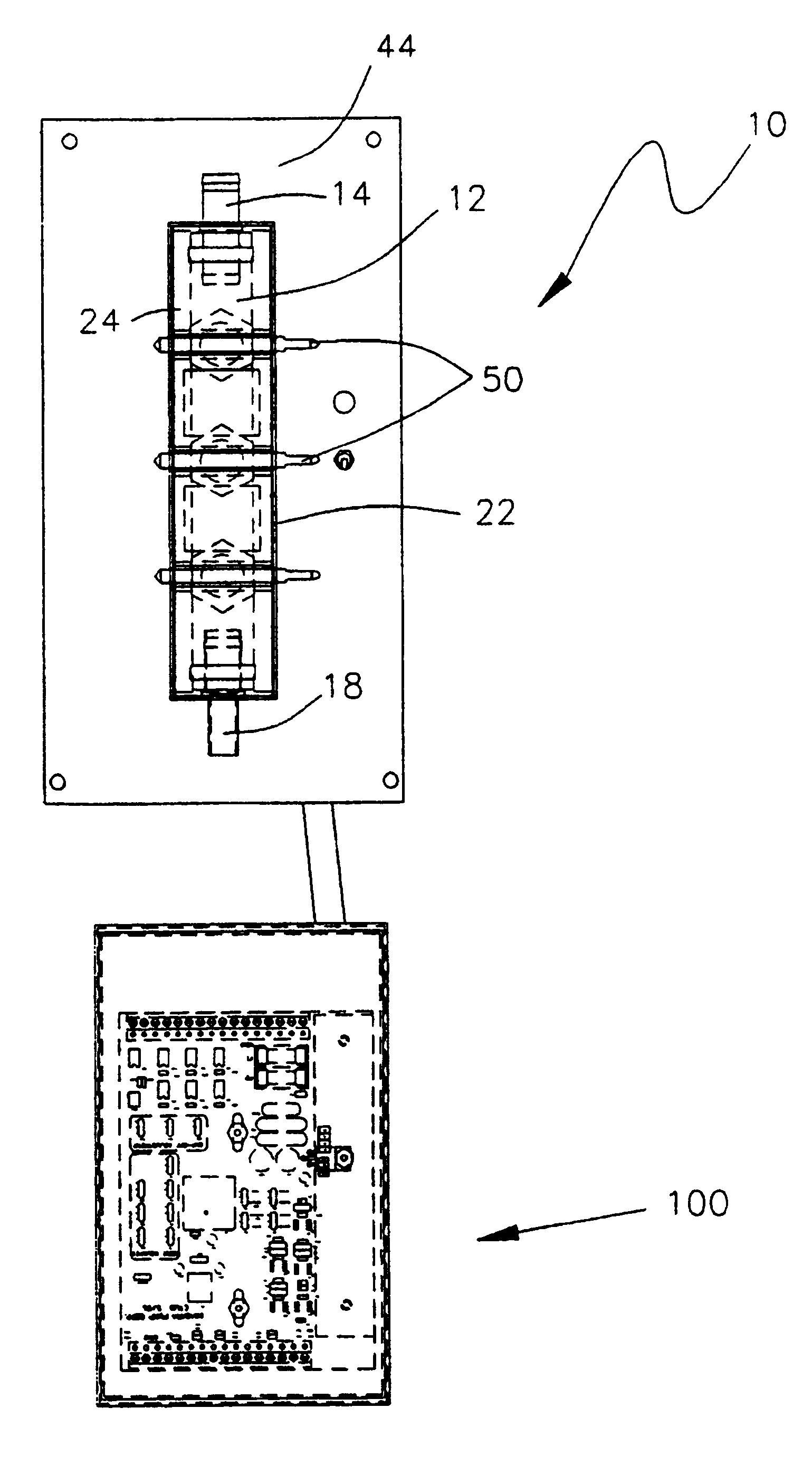
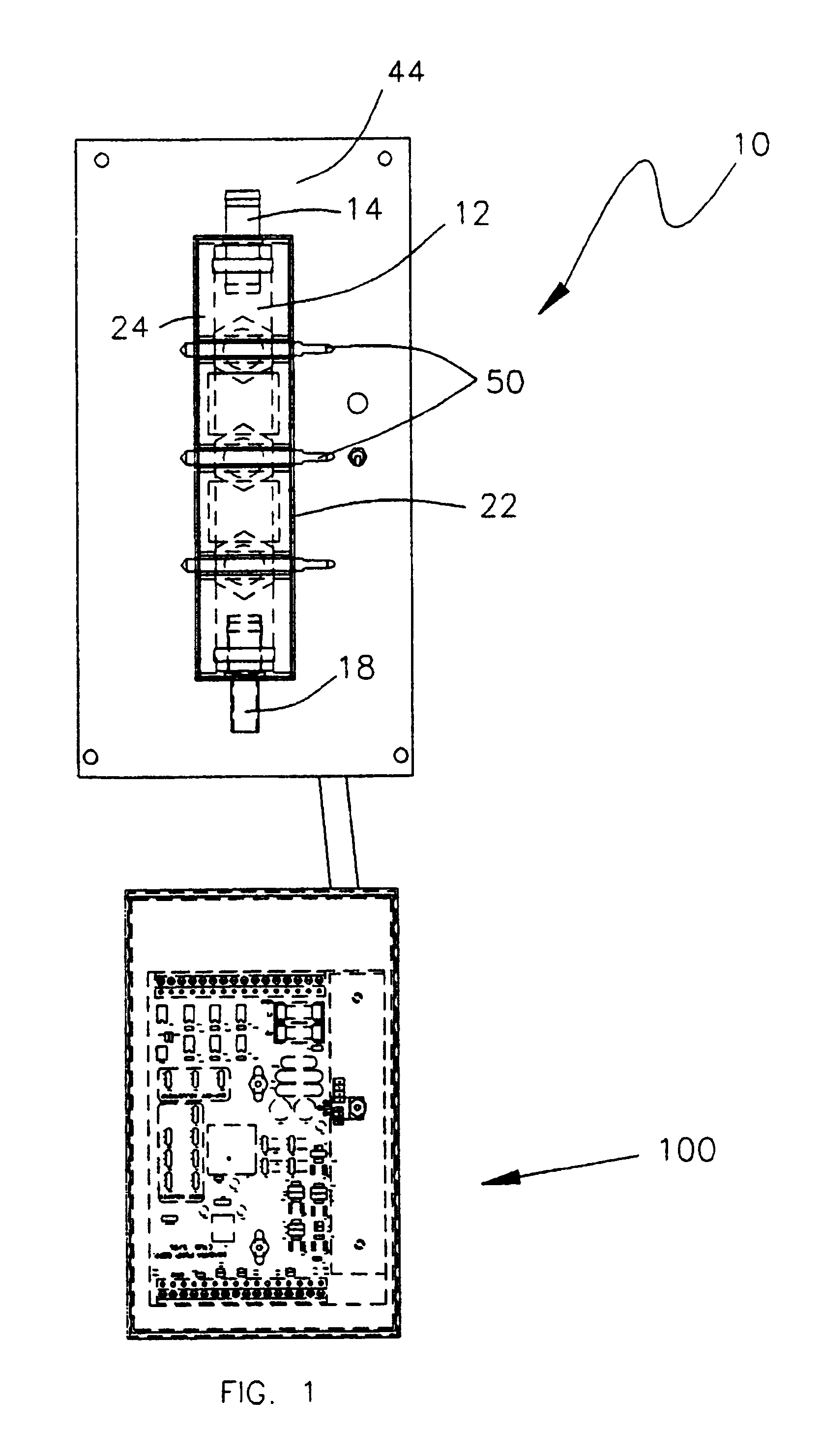
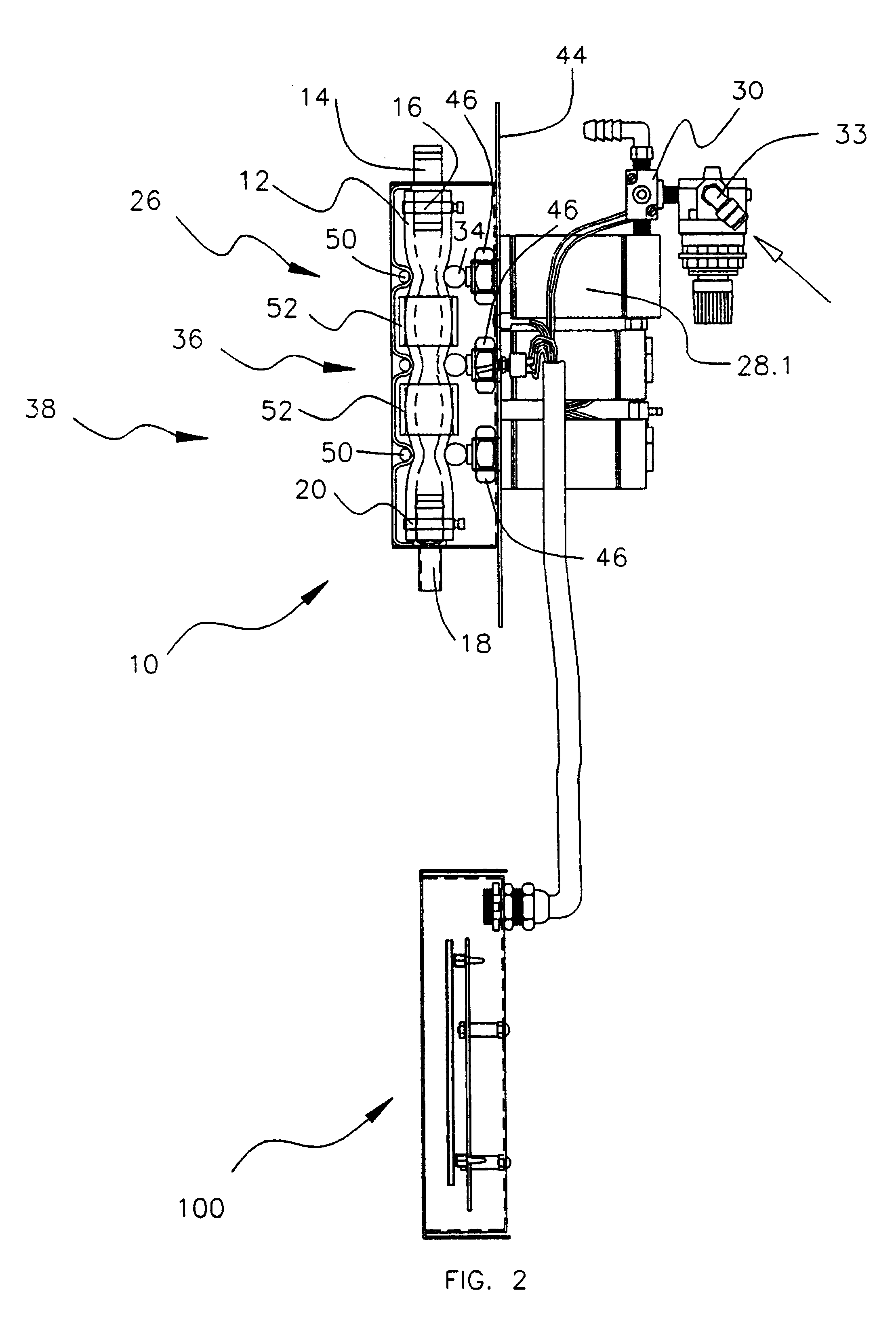
The unique benefits of this method of construction of this first embodiment of the invention are several. First, when the top plate 24 is pushed down upon the pump hose 12, the hose is partially and symmetrically compressed between the anvils 34 and 24.1, as can best be seen from FIG. 5A. This firmly captures the tube 12 such that the ends are captured by the hose fittings, and intermediate portions of the tube at each matched and symmetrical anvil position. As will be shown, this partial symmetrical compression and highly defined capture of the tube at the points noted is critical to the beneficial operation of the present invention. Second, the means of attachment of the top plate also assures that the assembly is made to a precisely predetermined dimensional relationship relative to a particular size pump tube and a particularly sized embodiment of the pump. Third, the means of attachment also assures a very simple and self evident procedure for assembly and one which can be visu...

second embodiment

The second embodiment of the linear peristaltic pump apparatus of this invention, which is shown in FIGS. 32-35, uses check valves 212 and 216 instead of the occlusive valves of the first embodiment, and is modified in other ways. The second embodiment is more fully described in applicants copending U.S. provisional patent application Ser. No. 60 / 040,232, filed Mar. 11, 1997, the subject matter of which is incorporated herein by reference thereto. Briefly, the check valve pump apparatus consists of a suitable infeed check valve assembly 212 connected to one end of a short section of high durometer flexible tubing 214 of the same type employed above, with an outfeed check valve assembly 216 connected to the other end. The check valves, which allow fluid flow in only one direction, are fitted such that both allow flow in the same direction. Disposed between the two check valves is a pneumatically operated displacement assembly 218. Each of the valves 212 and 216 are essentially identi...


PUM


Abstract

A liquid pumping apparatus for pumping liquids, more specifically a linear peristaltic pump apparatus. The apparatus consists of a high durometer compressible elastomeric liquid flow tube (12), an infeed valve assembly (26), an outfeed valve assembly (38), an extensible and retractable actuator anvil (34) having a round surface which engages the flow tube (12) at all times, an opposed anvil (24.1) having a round surface in engagement with the flow tube at all times, the flow tube being held between the anvils (34, 24.1) in a slightly compressed state when the anvil (34) is retracted, and a control assembly (100) for causing the movable anvil to be sequentially extended and retracted to cause flow within the flow tube (12) from the infeed valve assembly (26) to the outfeed valve assembly (38). With this apparatus the lumen of the flow tube (12) to the sides of the anvils is not completely reduced to zero volume during displacement compression whereby gas embolisms do not erupt or explode when discharged. Two principal embodiments are disclosed, one having infeed and outfeed check valves which oclude the flow tube, and the other having check valves.

Description

The present invention relates generally to a liquid pumping apparatus. More specifically, it relates to a linear peristaltic pump apparatus, also termed a tube pump or a hose pump.Peristaltic pumps may be conveniently subdivided into two major types, rotary or roller types, and linear or in-line types. Rotary types are frequently encountered in laboratory, instrumentation and light commercial settings. Rotary peristaltic pumps, in which compressive elements, generally rollers, fully occlude a flexible tube as them move in a circumferential, circular arc over tubing which is supported by a circular backstop, are known to offer very limited tubing life and generally are capable of pumping only low viscosity liquids at very low discharge pressures and at very modest flow rates. As the compressive elements move over the tubing, the tubing is subjected not only to occlusive crushing but also to a stretching action along the flow axis of the tubing. This fundamental design characteristic ...

Claims


Application Information

Patent Timeline
IPC IPC(8): F04B49/06F04B43/113F04B43/00F04B13/02F04B13/00
CPCF04B13/02F04B43/0072F04B43/1133F04B43/1136F04B49/065A61M5/14228F04B2201/0201F04B2201/0206F04B2201/0601F04B2203/1001F04B2205/09
Inventor PHALLEN, IVER J.VOGT, DOUGLAS N.
Owner NIAGARA PUMP CORP
Why Eureka
Try Eureka