Vibration reduction in a combustion chamber

a technology of vibration reduction and combustion chamber, which is applied in the ignition of turbine/propulsion engines, combustion types, lighting and heating apparatuses, etc., can solve the problems of putting the mechanical integrity of the machine at risk, the difficulty of stabilizing the flame, and the installation of further resonators designed for these frequencies

Inactive Publication Date: 2002-11-07
ALSTOM TECH LTD
View PDF0 Cites 20 Cited by
  • Summary
  • Abstract
  • Description
  • Claims
  • Application Information

AI Technical Summary

Problems solved by technology

Such a pressure vibration is designated as a selfexcited combustion chamber pulsation or as instability and presents a serious problem in modern industrial gas turbines since these use premixing combustion.
However, this lean combustion also necessitates a low flame temperature and makes it difficult to stabilize the flame.
The pressure amplitudes resulting from these combustion pulsations may at...

Method used


Image

  • Vibration reduction in a combustion chamber
  • Vibration reduction in a combustion chamber
  • Vibration reduction in a combustion chamber

Examples


Embodiment Construction

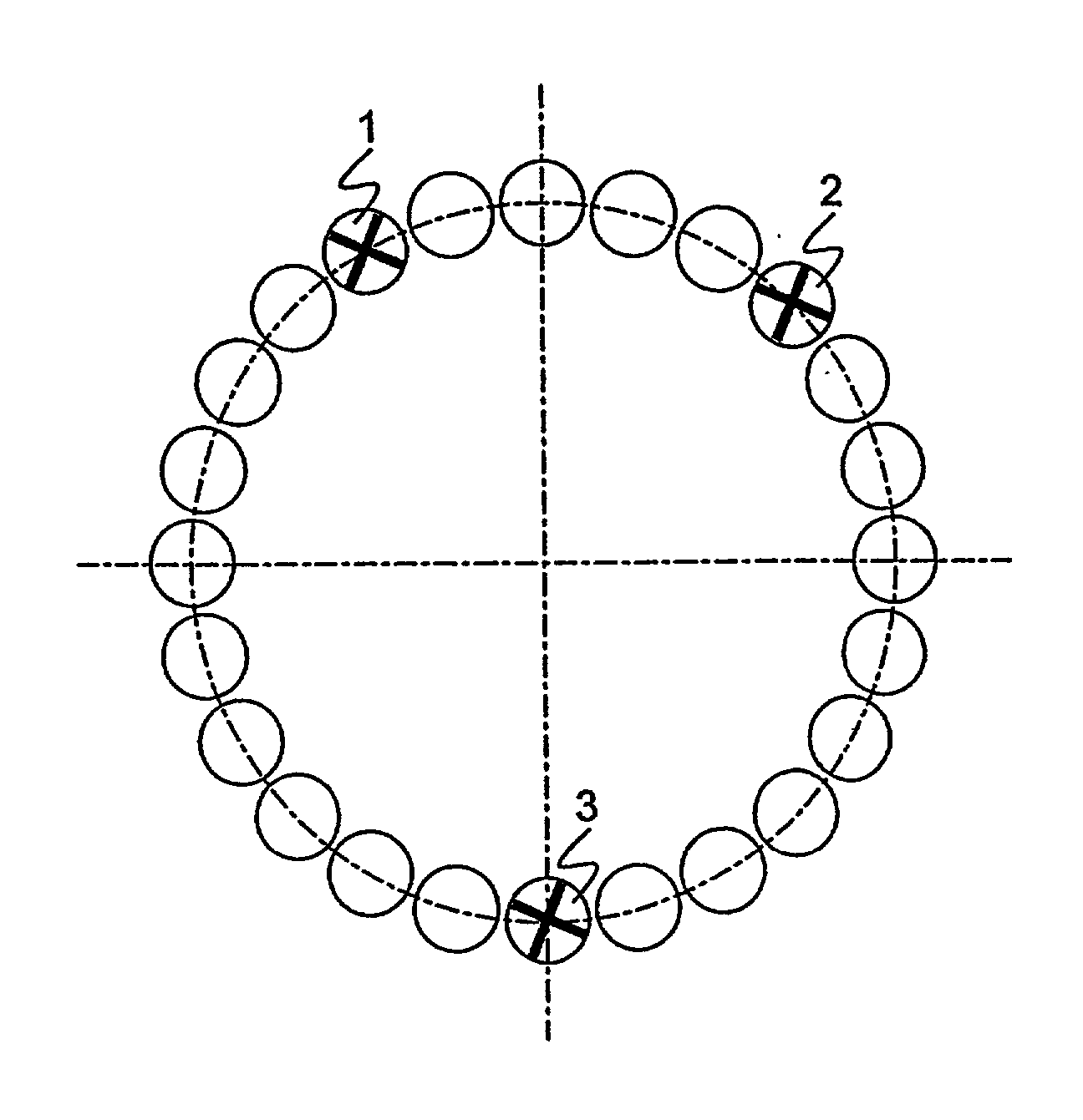
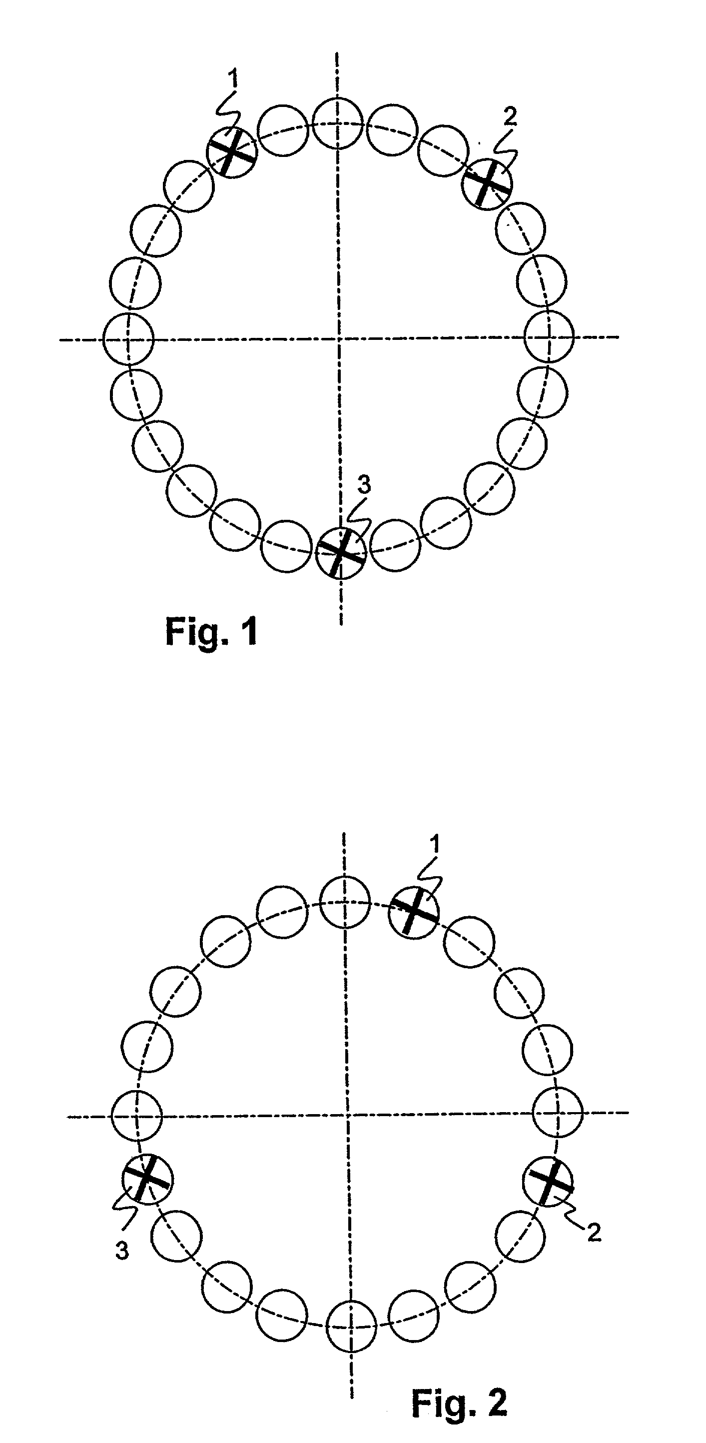
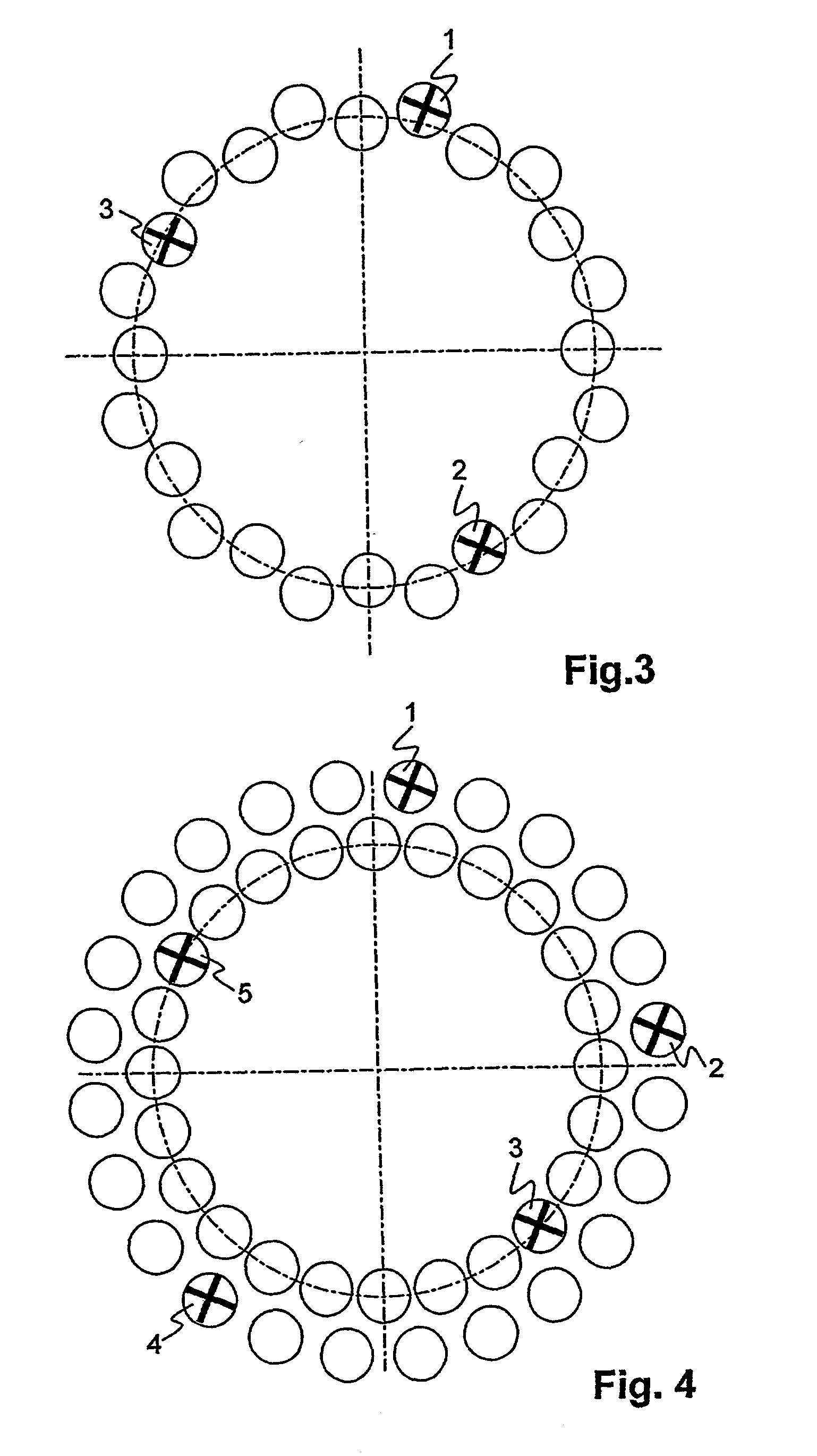
[0025] FIG. 1 shows diagrammatically an annular arrangement of burners of an annular combustion chamber with 24 burners. Burners are illustrated diagrammatically by circles, and modulatable burners 1, 2, 3 are illustrated by circles with a cross. The combustion chamber is part of a thermal turbomachine, in particular an industrial gas turbine. The combustion chamber is preferably an annular or else an annular-tube combustion chamber, that is to say its firing space surrounds a rotor of the gas turbine.

[0026] What is meant below by a burner or individual burner is a system for the supply of fuel, for introducing the fuel into a working medium, for mixing the fuel with the working medium and, if appropriate, for stabilizing a flame. To fulfill these functions, a burner has, for example, a flame tube, an arrangement for the swirl stabilization of the flame or a fuel lance. In the case of a modulatable burner 1, 2, 3, a means for modulating the fuel mass flow is likewise considered as a...


PUM


Abstract

A combustion chamber according to the invention has a number b0 of annularly arranged burners, of which a number k of modulatable burners have means for modulating a fuel mass flow, k being k<b0, and the modulatable burners being arranged in such a way that between every pair of adjacent modulatable burners are arranged in each case a1, a2, . . . ak nonmodulatable burners, and that the values a1+1, a2+1, . . . , ak+1 are not integral divisors of b0. In a preferred embodiment of the invention, a highest value of <paragraph lvl="0"><in-line-formula>LCM(b0, a1+1), LCM(b0, a2+1), . . . LCM(b0, ak+1) </in-line-formula>is maximum, LCM designating the lowest common multiple. It thereby becomes possible to damp a maximum number of azimuthal vibration modes of the combustion chamber by means of a minimum number of modulatable burners. Each pair of modulatable burners gives rise to at least one undesirable vibration or instability which, however, is damped by the other modulatable burner or burners arranged according to the invention.

Description

[0001] The invention relates to the field of thermal turbomachines. It relates to a combustion chamber and to a method for the reduction of thermoacoustic vibrations in a combustion chamber according to the preambles of patent claims 1 and 9 respectively.PRIOR ART[0002] In annular combustion chambers of turbomachines, under specific operating states selfexcited pressure vibrations are formed, which are caused by the influence on one another of thermoacoustic pressure pulsations and a local release of heat. Such a pressure vibration is designated as a selfexcited combustion chamber pulsation or as instability and presents a serious problem in modern industrial gas turbines since these use premixing combustion. In premixing combustion, a fuel and air are intermixed as homogeneously as possible before combustion and are ignited only after mixing. Combustion is to be as lean as possible, in order to reduce NOx emissions. However, this lean combustion also necessitates a low flame temper...

Claims


Application Information

Patent Timeline
IPC IPC(8): F23D11/36
CPCF23D2210/00F23D11/36
Inventor WEISENSTEIN, WOLFGANG
Owner ALSTOM TECH LTD
Why Eureka
Try Eureka