Autonomous intelligent self-energy-supply active suspension adopting double-head oil cylinder and working method of autonomous intelligent self-energy-supply active suspension

A double-head oil cylinder and active suspension technology, applied in suspension, elastic suspension, vehicle spring, etc., can solve the problems of complex rectification oil circuit, inability to intelligently switch between comfort and driving safety, and improve driving safety , the effect of improving ride comfort

Pending Publication Date: 2022-05-06
尨腾汽车科技(南京)有限公司
1 Cites 1 Cited by

AI-Extracted Technical Summary

Problems solved by technology

[0004] The purpose of the present invention is to solve the problem that the anti-resonance vibration damping structure of the above-mentioned self-powered active suspension uses a single-head oil cylinder to provide equal damping and other inertia, which requires complex rectification oil circuits, and can not achieve intelligence between the ride comfort and driv...

Method used

As shown in Figure 8, on the basis of the structure of Figure 1, a second throttle valve 24 is connected in parallel at both ends of the parallel oil circuit formed by the intelligent control switch 13 and the electromagnetic valve 14, which can reduce the pressure of the present invention. The autonomous intelligent self-powered active suspension damping can intelligently reduce the inertia of the oil circuit. When it works, when the solenoid valve 14 is closed, the second throttle valve 24 works in parallel with the inner measuring hole f to provide greater damping. When the damping provided by the second throttle valve 24 alone is 1, the damping provided by the inner metering hole f alone is 2 to 10. Therefore, the damping provided by the second throttle valve 24 alone is the same as that provided by the second throttle valve 24 alone. The ratio of the damping provided by the inner metering hole f is 1:2~10, so that the larger damping provided by the parallel connection between the second throttle valve 24 and the inner metering hole f is mainly provided by the second throttle valve 24, which can reduce oil flow. The degree of influence of the inertia capacity generated by the excess inner hole f on the inertia value of the entire oil circuit.
When the autonomous intelligent self-supply active suspension of the present invention is installed on the vehicle, each wheel has an autonomous intelligent self-supply active suspension, and four autonomous intelligent self-supply suspensions c...

Abstract

The invention discloses an autonomous intelligent self-energy-supply active suspension adopting a double-head oil cylinder and a working method, and belongs to the field of automobiles, the autonomous intelligent self-energy-supply active suspension comprises a traditional vibration reduction structure and an anti-resonance vibration reduction structure, the anti-resonance vibration reduction structure is provided with the double-head oil cylinder, and the double-head oil cylinder is composed of a second oil cylinder arranged up and down and a second piston with piston rods at the upper end and the lower end; the upper portion of an upper oil cavity of the second oil cylinder is sequentially connected with an inerter spiral pipe, an intelligent control switch and the lower portion of a lower oil cavity of the second oil cylinder through a hydraulic pipeline, and the two ends of the intelligent control switch are connected with a normally-closed electromagnetic valve which is closed in a delayed mode in parallel. The intelligent control switch automatically changes the equal-inertial-capacity value and the equal-damping value of the anti-resonance vibration reduction structure along with changes of the vibration frequency of the automobile, when the vibration frequency of the automobile is low, large equal-inertial-capacity and equal-damping are provided to improve the driving safety, and when the vibration frequency of the automobile is high, small equal-inertial-capacity and equal-damping are provided to improve the riding comfort.

Application Domain

Resilient suspensionsVehicle springs

Technology Topic

Driving safetySmart control +8

Image

  • Autonomous intelligent self-energy-supply active suspension adopting double-head oil cylinder and working method of autonomous intelligent self-energy-supply active suspension
  • Autonomous intelligent self-energy-supply active suspension adopting double-head oil cylinder and working method of autonomous intelligent self-energy-supply active suspension
  • Autonomous intelligent self-energy-supply active suspension adopting double-head oil cylinder and working method of autonomous intelligent self-energy-supply active suspension

Examples

  • Experimental program(1)

Example Embodiment

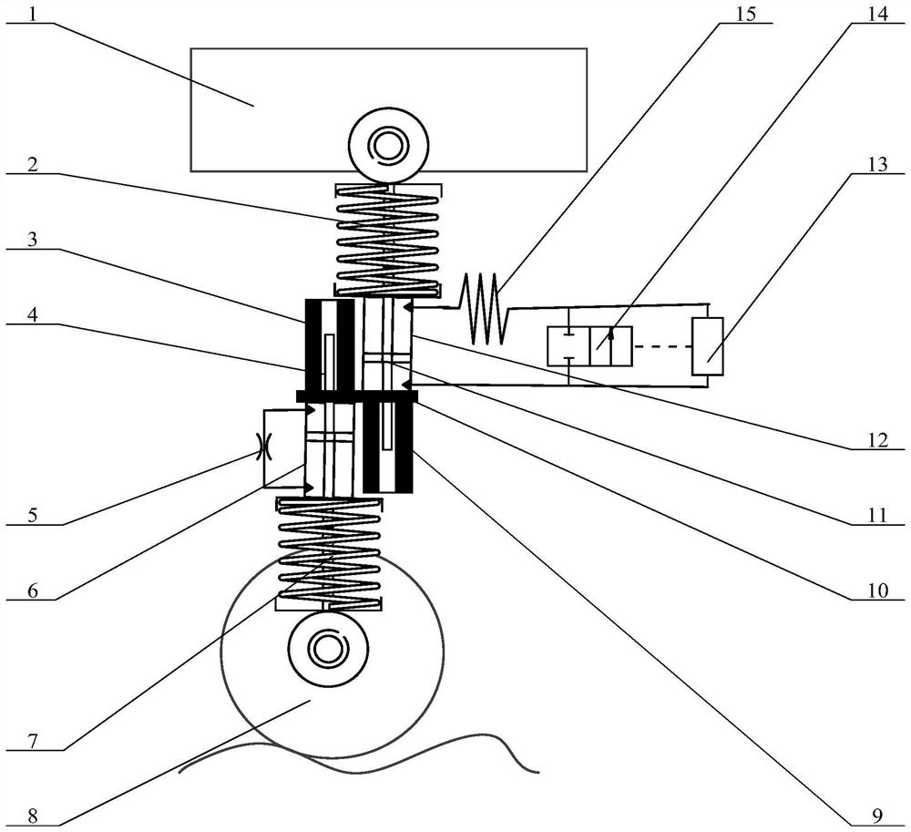
[0026] like figure 1 As shown, the autonomous intelligent self-powered active suspension adopting double-head oil cylinders of the present invention is installed between the wheels 8 and the vehicle body 1 above the wheels 8, including traditional damping structures and anti-resonance damping structures.
[0027] Wherein, the traditional damping structure has a first coil spring 7 , a first throttle valve 5 and a first oil cylinder 6 . The first oil cylinder 6 is arranged up and down, and the first piston 4 separates the first oil cylinder 6 into the upper and lower two sealed oil chambers inside the first oil cylinder 6, and oil is stored in the upper and lower oil chambers; the first piston The upper and lower ends of 4 are all piston rod ends, that is, there are rod ends, and there are two piston rods. In this way, the first oil cylinder 6 and the first piston 4 with two piston rods form a double-headed oil cylinder. Therefore, the first The piston 4 divides the first oil cylinder 6 into two closed upper and lower oil chambers with equal cross-sectional areas. The upper part of the upper oil chamber is connected in series with the first throttle valve 5 to the lower part of the lower oil chamber through a hydraulic pipeline, forming a closed oil chamber with a traditional damping structure. road. The upper end of the upper piston rod of the first piston 4 stretches upwards outside the first oil cylinder 6, and a first protective sleeve 3 is sheathed outside the upper piston rod outside the first oil cylinder 6 to protect the upper piston rod. The lower end of the lower piston rod of the first piston 4 protrudes downwards outside the first oil cylinder 6 and is fixedly connected with the wheel 8 below through a bush. The first helical spring 7 arranged up and down is arranged in the space of the wheel 8 and the lower part of the first oil cylinder 6, the upper end of the first helical spring 7 is rigidly connected with the cylinder body of the first oil cylinder 6, and the lower end of the first helical spring 7 is fixedly connected At the lower end of the lower piston rod of the first piston 4.
[0028]Wherein, the anti-resonance damping structure has a second coil spring 2 , an inertia helical tube 15 , a solenoid valve 14 , an intelligent control switch 13 and a second oil cylinder 12 . The second oil cylinder 12 is arranged up and down, and the second piston 11 separates the second oil cylinder 12 into upper and lower two sealed oil chambers inside the second oil cylinder 12, and oil is stored in the upper and lower oil chambers. The upper and lower ends of the second piston 11 are all piston rods, that is, there are rod ends, and there are two piston rods. Like this, the second oil cylinder 12 and the second piston 11 with two piston rods form a double-headed oil cylinder. The structure of the head oil cylinder is the same as that of the double head oil cylinder in the traditional damping structure. Therefore, the second piston 11 divides the second oil cylinder 12 into two sealed oil chambers, upper and lower, with equal cross-sectional areas. The upper part of the upper oil chamber of the second oil cylinder 12 is sequentially connected with the inertial helical tube 15, the intelligent control switch 13 and the lower part of the lower oil chamber of the second oil cylinder 12 by the hydraulic pipeline, and a solenoid valve 14 is connected in parallel at both ends of the intelligent control switch 13, The solenoid valve 14 is a normally closed delay closing solenoid valve. The intelligent control switch 13 is connected to the normally closed solenoid valve 14 through a control line to control the opening of the solenoid valve 14, thus forming an anti-resonance damping structure to close the oil circuit. The upper piston rod of the second piston 11 protrudes upwards outside the second oil cylinder 12 and is fixedly connected with the vehicle body 1 . A second coil spring 2 is sleeved on the second piston 11 extending out of the second oil cylinder 12, the upper end of the second coil spring 2 is fixedly connected to the upper end of the upper piston rod of the second piston 11, and the lower end of the second coil spring 2 is connected to The cylinder body of the second oil cylinder 12 is rigidly connected.
[0029] The central axis of the first oil cylinder 6 is parallel to the central axis of the second oil cylinder 12, and they are staggered one by one. The upper end of the first oil cylinder 6 and the lower end of the second oil cylinder 12 are fixedly connected to the middle connecting plate 10.
[0030] The upper piston rod of the first piston 4 passes through the upper end of the cylinder body of the first oil cylinder 6 and the intermediate connecting plate 10 upwards and then extends into the first protective cover 3. The first protective cover 3 is a hollow rigid cylinder, and the first protective cover 3 is a hollow rigid cylinder. An oil cylinder 6 cylinder bodies are coaxial, and are fixedly installed on the upper side of the intermediate connecting plate 10 . The lower piston rod of the second piston 11 passes through the lower end of the cylinder block of the second oil cylinder 12 and the intermediate connecting plate 10 downwards and then extends into the shaft hole of the second protective sleeve 9, which is a hollow rigid cylinder. , coaxial with the second oil cylinder 12 cylinder body, fixedly installed on the lower side of the middle connecting plate 10.
[0031] Therefore, the autonomous intelligent self-powered active suspension described in the present invention adopts the intermediate connecting plate 10 to non-coaxially connect the traditional damping structure and the anti-resonance damping structure in series from bottom to top, the intermediate connecting plate 10, the first protective cover 3 and the The sum of the masses of the second protective sheath 9 together forms the third mass of the suspension.
[0032] like figure 2 As shown, the intelligent control switch 13 has a valve body 16, the valve body 16 is a hollow structure, the two ends of the valve body 16, one end is the oil inlet a, the other end is the oil outlet e, from the oil inlet a to the outlet Between the oil port e are the outer metering hole b and the spool chamber d in turn. The diameter of the outer metering hole b is smaller than that of the oil inlet a and the spool chamber d, and the diameter of the spool chamber d is larger than that of the oil inlet a and the oil outlet The aperture of mouth e. The oil inlet a, the outer measuring hole b, the valve core chamber d and the oil outlet e penetrate the entire valve body 16 from one end to the other end of the valve body 16 .
[0033] The inner walls of the oil inlet a and the oil outlet e are provided with threads, the oil inlet a is fixedly connected with the external oil pipe through threads, the oil outlet e is fixedly connected with one end of the valve body joint 20 through threads, and the valve body joint 20 is opened There is a through hole, and the other end of the valve body joint 20 is fixedly connected with an external oil pipe through threads.
[0034] On the side wall of the valve body 16, there is a valve casing contact slot c, which communicates with the valve core chamber d and is close to the end of the outer measuring hole b.
[0035] The intelligent control switch 13 also has a delayed disconnection trigger switch 23, which is arranged on the side of the contact piece groove c of the valve housing and outside the side wall of the valve body 16, and the delayed disconnection trigger switch 23 is fixedly connected to the valve body 16 Outside the side wall, the switch contacts of the delay-off trigger switch 23 extend from the outside to the inside of the valve core chamber d through the valve housing contact groove c, and at the same time, the delay-off trigger switch 23 is connected to the normally closed electromagnetic valve via wires. Valve 14, when the switch contact piece of the delayed disconnection trigger switch 23 moves from the oil inlet a to the oil outlet e, the delayed disconnection trigger switch 23 works, triggers the solenoid valve 14, and the solenoid valve 14 opens, otherwise, When the contact piece of the delayed disconnection trigger switch 23 moves from the oil outlet e to the oil inlet a direction, that is, when the contact piece is reset.
[0036] The intelligent control switch 13 also has a spool 22 and a preload spring 18. The spool 22 and the preload spring 18 are arranged inside the spool chamber d. One end of the spool 22 extends into the outer measuring hole b in the axial direction, and One end is covered with a preload spring 18 , one end of the preload spring 18 is supported on the spool 22 , and the other end is supported on the valve body joint 20 , the preload spring 18 exerts a preload spring force on the spool 22 . The central axes of the outer measuring hole b, the spool chamber d, the spool 22 and the preload spring 18 are collinear. The direction of the preload spring force applied by the preload spring 18 to the spool 22 and the direction of the switch contact piece trigger switch of the delay disconnection trigger switch 23 are facing each other, and when the hydraulic oil flows through the spool 22, the spool 22 Overcoming the spring force of the preload spring 18, it moves back and forth inside the outer measuring hole b and the spool chamber d, driving the switch contacts of the delayed disconnection trigger switch 23 to connect the solenoid valve 14.
[0037] like Figure 4 The shown spool 22 has a circular boss i in the middle, and both axial ends of the circular boss i extend a circular valve needle axially, which are respectively the first valve needle j and the second valve needle k , the first valve needle j is close to the outer measuring hole b and extends into the outer measuring hole b, the circular boss i and the second valve needle k are in the valve core chamber d, and the second valve needle k is covered with a preload spring 18 . The outer diameter of the circular boss i is greater than the outer diameters of the first needle j and the second needle k, but smaller than the inner diameter of the valve core chamber d, and the outer diameters of the first needle j and the second needle k are the same . The middle of the valve core 12 is provided with an axially penetrating internal measuring hole f, that is, the internal measuring hole f passes through the first valve needle j, the circular boss i and the second valve needle k. More than one axially arranged oil guide hole g is opened on the circular boss i outside the first valve needle j and the second valve needle k, the oil guide hole g passes through the circular boss i, and is connected with the inner measuring hole f parallel. The distance between the center of the oil guide hole g and the center of the inner gauge hole f is greater than the radius of the outer gauge hole b, so that the oil guide hole g is located outside the outer gauge hole b.
[0038] On the side wall of the circular boss i, there is a valve core contact groove h, and its notch faces the valve housing contact groove c on the valve core chamber d. The valve core contact groove h and the valve housing contact groove c The positions are corresponding and connected. The switch contact piece of the delay disconnection trigger switch 23 is inserted into the contact piece groove h of the spool from the outside to the inside through the contact piece groove c of the valve housing, so when the spool 22 moves back and forth, the switch contact piece can be pressed and reset , so that the delayed opening trigger switch 23 is opened and delayed closed, thereby controlling the normally closed solenoid valve 14 .
[0039] like Figure 5 As shown, in order to increase the length of the inner metering hole f, the inner metering hole f adopts a continuous folding hole with no less than 1 fold.
[0040] like figure 2 , 3 , 4, one or more small oil seals 21 are set between the side wall of the first valve needle j and the wall of the outer measuring hole b, so that the sealing connection between the first valve needle j of the spool 22 and the outer measuring hole b , the oil can only enter the spool chamber d through the inner measuring hole f. A plurality of large oil seals 17 are arranged between the side wall of the circular boss i and the inner wall of the spool chamber d, and the circular boss i of the spool 22 is in sealing connection with the spool chamber d. One or more adjusting gaskets 19 are arranged between the preload spring 18 and the valve body joint 20, and under the action of the preload spring 18, the end surface of the circular boss i close to the end of the outer measuring hole b is tightly fitted On the corresponding end surface of the spool chamber d, at this time, the side wall h1 on the spool contact groove h near the outer measuring hole b is aligned with the side wall c1 on the valve casing contact groove c near the outer measuring hole b, see Image 6 The positions of the side wall h1 and the side wall c1 shown in , at this time, the switch contacts of the delayed opening trigger switch 23 are closely attached to the side wall h1 and the side wall c1.
[0041] see Figure 1-6 , when the vehicle starts to vibrate under the action of road irregularity excitation, steering centrifugal force, acceleration inertial force or deceleration inertial force, the first piston 4 generates relative motion relative to the first oil cylinder 6, and the upper oil chamber and the lower oil chamber of the first oil cylinder 6 The oil in the cylinder flows back and forth through the first throttle valve 5. Since a double-headed oil cylinder is used, the cross-sectional areas of the upper oil chamber and the lower oil chamber of the first oil cylinder 6 are equal, so that the first throttle valve 5 is opposite to the first piston 4. Equal damping is provided when the first oil cylinder 6 moves relative to each other. When the second piston 11 moves relative to the second oil cylinder 12, the oil in the upper oil chamber and the lower oil chamber of the second oil cylinder 11 passes through the inertia coil 15, the inner measuring hole f of the intelligent control switch 13 and the normally closed The parallel oil circuit formed by the solenoid valve 14 flows back and forth. Since the second oil cylinder 12 is a double-headed oil cylinder, the cross-sectional areas of the upper oil chamber and the lower oil chamber are equal, so that the inertia spiral tube 15 is in the position of the second piston 11 relative to the second oil cylinder. When the oil cylinder 12 moves relative to each other, it provides equal inertia and less equal pipeline loss damping along the way.
[0042] When the second piston 11 starts to move upward relative to the second oil cylinder 12, the solenoid valve 14 is in a closed state, and the hydraulic oil is supplied from the upper oil chamber of the second oil cylinder 12 through the inner measuring hole on the inertial coil tube 15 and the intelligent control switch 13. f flows to the lower oil chamber of the second oil cylinder 12. When the oil flows through the inertial helical tube 15, the pressure difference between the two ends of the inertial helical tube 15 is generated, and a small pressure difference is generated along the damping loss of the helical tube, that is, the inertial helical tube 15 The two ends not only generate the pressure difference of the helical tube inertia inertial force related to the relative motion acceleration of the second piston 11, but also produce a small pressure difference of the helical tube damping loss along the process related to the relative motion speed of the second piston 11. Therefore, the inertia The pressure difference between the two ends of the helical tube 15 is equal to the sum of the pressure difference of the inertial force of the helical tube and the pressure difference of the damping loss along the helical tube. When the oil flows through the inner metering hole f, the two ends of the elongated inner metering hole f not only produce a large pressure difference of the damping loss along the course of the inner metering hole, but also the pressure difference of the damping loss along the course of the inner metering hole is the same as that of the second piston 11 The relative motion speed is related, and the pressure difference of the inertial force of the inner metering hole is also generated. The pressure difference of the inertial force of the inner metering hole is related to the relative motion acceleration of the second piston 11. Therefore, the pressure difference at both ends of the inner metering hole f is equal to the damping along the inner metering hole The sum of the loss pressure difference and the inertial force pressure difference of the inner volume hole.
[0043] When the sum of the pressure difference generated by flowing through the inner metering hole f is greater than the sum of the preload force of the preload spring 18 and the trigger opening force of the switch contact piece of the delay disconnection trigger switch 23, under the oil pressure, the spool 22 is relatively open to the valve. The body 16 moves down a very small stroke, that is, the relative position of the valve body 16 and the valve core 22 is determined by Image 6 change to Figure 7 , Figure 7 In this process, the side wall h1 on the contact piece groove h of the spool moves toward the direction of the oil outlet hole e, and the switch contact piece on the trigger switch 23 is pressed down to turn on the solenoid valve 14, so that the normally closed solenoid valve 14 is opened. The oil flows through the solenoid valve 14 from the upper oil chamber of the second oil cylinder 12 to the lower oil chamber. At this time, only the inertial helical tube 15 provides the helical tube inertial inertia damping force and a small The helical tube damps the shock absorbing force along the way. The solenoid valve 14 is a normally closed delay closing solenoid valve, and the delay closing time is 0.2-1s. When the oil passes through the solenoid valve 14, due to the delay of the solenoid valve 14, the pressure of the inner metering hole f decreases. Under the action of the preload spring 18, the relative position of the valve body 16 and the valve core 22 is changed by Figure 7 The state of the Image 6 state, the switch contacts of the trigger switch 23 are delayed and restored, and only the inertial helical tube 15 provides the anti-resonance vibration damping structure with the helical tube inertial vibration damping force and the smaller helical tube along the way. force. After the delayed closing of the solenoid valve 14, when the sum of the damping force of the inner metering hole and the inertial inertia force generated by flowing through the inner metering hole f is greater than the preloading force of the preloading spring 18 and the contact piece of the delayed disconnection trigger switch 23 is triggered to open When the force is summed, the solenoid valve 14 is opened again, and the inertial helical tube 15 continues to provide the anti-resonance vibration damping structure with the helical inertial inertial vibration damping force and the smaller helical tube along the way damping vibration damping force, so that the cycle works, Automatically change the constant inertia value and constant damping value provided by the anti-resonance damping structure to improve driving safety and ride comfort.
[0044] Reducing the cross-sectional area of ​​the first valve needle j can reduce the stiffness of the preload spring 18 to improve the response sensitivity of the intelligent control switch 13 . The number of adjusting shims 19 is increased or decreased to change the preload spring force of the preload spring 18 , thereby changing the vibration frequency of whether the solenoid valve 14 is opened or not.
[0045]Since the relative motion acceleration of the second piston 11 is proportional to the square of its vibration frequency, and the relative motion speed of the second piston 11 is only proportional to its vibration frequency, therefore, when the relative motion frequency of the second piston 11 increases, the inner measuring hole f is generated The increasing speed of the inertial force of inertia is much faster than that of the damping force, that is, the inertial force generated by the inner measuring hole f is more sensitive to the relative motion frequency of the second piston 11. Therefore, whether the solenoid valve 14 is opened or not is mainly It is determined by the preload spring force of the preload spring 18 and the relative movement frequency of the second piston 11 .
[0046] By working in this way, when the vehicle vibrates with a small frequency under the action of steering centrifugal force, acceleration inertial force, or deceleration inertial force, the second piston 11 moves at a low frequency, and the anti-resonance damping structure is controlled by the inertia helical tube 15 and intelligent control. The inner measuring holes f of the switch 13 jointly provide equal inertia and larger equal damping, because better safety can be obtained. When the vehicle vibrates at a higher frequency under the action of a larger road surface roughness, the second piston 11 moves at a higher frequency, and the anti-resonance damping structure is only provided by the inertia helical tube 15 with equal inertia and smaller equal damping , so better ride comfort can be obtained.
[0047] when using as Figure 5 When the folded inner metering hole f is not less than 1 fold as shown, the flow cross-sectional area of ​​the inner metering hole f is increased under the condition that the damping coefficient remains unchanged, that is, when Figure 5 The flow cross-sectional area of ​​the inner measuring hole f shown is larger than Figure 4 When the flow cross-sectional area of ​​the inner metering hole f is shown, the inertial capacity of the inner metering hole f generated by the inner metering hole f can be increased while the damping coefficient remains unchanged. Therefore, under the same relative motion condition of the second piston 11 , the inertia inertial force is generated by increasing the length of the inner measuring hole f, so as to improve the sensitivity of the intelligent control switch 13 to the motion frequency response of the second piston 11 .
[0048] like Figure 1-3 As shown, when the intelligent control switch 13 is connected to the external oil circuit, there are two ways to connect it, the first one is as follows figure 1 In the connection structure shown, the oil inlet a is connected to the inertial spiral tube 15 , and the oil outlet e is connected to the lower oil chamber of the second oil cylinder 12 . The second is to make the intelligent control switch 13 reverse, that is, the oil inlet a is connected to the lower oil chamber of the second oil cylinder 12, and the oil outlet e is connected to the inertial spiral tube 15; therefore, when the intelligent control switch 13 is connected to the external oil circuit They are connected in opposite directions. For the spool 22, its inlet and outlet are opposite, and the inner measuring hole f runs through the inlet and outlet of the spool 22 all the time.
[0049] When the intelligent control switch 13 adopts the second connection mode, when the second piston 11 starts to move downward relative to the second oil cylinder 12, the solenoid valve 14 is in a closed state, and the hydraulic oil is controlled by the lower oil chamber of the second oil cylinder 12, intelligently The inner metering hole f on the spool 22 of the switch 13 and the inertia helical tube 15 flow to the upper oil chamber of the second oil cylinder 12 . When the oil flows through the inner metering hole f, the two ends of the inner metering hole f not only produce a large pressure difference for the damping loss along the inner metering hole, but also generate a pressure difference for the inertial force of the inner metering hole. When the oil flows through the inertial helical tube 15, the two ends of the inertial helical tube 15 not only produce a pressure difference of the inertial force of the helical tube, but also a small pressure difference for the damping loss along the helical tube. When the sum of the damping force and the inertial inertial force generated by the inner metering hole f is greater than the sum of the preloading force of the preloading spring 18 and the trigger opening force of the contact piece of the delay disconnection trigger switch 23, the spool 22 is relative to the valve body 16. Move up a very small displacement, the solenoid valve 14 is opened, and the oil flows through the solenoid valve 14 from the lower oil chamber of the second oil cylinder 12 to the upper oil chamber. Provide the helical pipeline inertia inertial vibration damping force and the small helical pipeline along the damping vibration damping force. Since the solenoid valve 14 is a normally closed delay closing solenoid valve, the delay closing time is 0.2-1s. After the solenoid valve 14 is opened, only the inertial helical tube 15 continues to provide the helical pipe inertial inertial vibration damping force for the anti-resonance damping structure. And the smaller spiral pipeline damping force along the way. After the solenoid valve 14 is closed, when the sum of the damping force and the inertial inertial force generated by flowing through the inner metering hole f is greater than the sum of the preload force of the preload spring 18 and the trigger opening force of the switch contact piece, the solenoid valve 14 is opened and continues Only the inertia helical tube 15 provides the anti-resonance vibration damping structure with the helical tube inertia inertial vibration damping force and the smaller helical tube along the way damping vibration damping force, so that the cycle works. By working in this way, when the automobile generates vibrations with a small frequency under the action of steering centrifugal force, acceleration inertial force, and deceleration inertial force, the second piston 11 moves at a low frequency, and the anti-resonance vibration damping structure is composed of inertial helical tube 15 and intelligent The inner measuring holes f of the control switch 13 jointly provide equal inertia capacity and greater equal damping, so as to achieve better safety. When the automobile generates high-frequency vibrations under the action of relatively large road surface roughness, the second piston rod 1 moves at a relatively high frequency, and the anti-resonance damping structure is provided by the inertial helical tube 15 with equal inertia and small vibration. Equal damping to achieve better ride comfort.
[0050] like Figure 8 shown in figure 1 On the basis of the structure, a second throttle valve 24 is connected in parallel at both ends of the parallel oil circuit composed of the intelligent control switch 13 and the electromagnetic valve 14, which can reduce the damping of the autonomous intelligent self-powered active suspension described in the present invention, and It can intelligently reduce the inertia of the oil circuit. When it works, when the solenoid valve 14 is closed, the second throttle valve 24 works in parallel with the inner measuring hole f to provide greater damping. When the damping provided by the second throttle valve 24 alone is 1, the damping provided by the inner metering hole f alone is 2 to 10. Therefore, the damping provided by the second throttle valve 24 alone is the same as that provided by the second throttle valve 24 alone. The ratio of the damping provided by the inner metering hole f is 1:2~10, so that the larger damping provided by the parallel connection between the second throttle valve 24 and the inner metering hole f is mainly provided by the second throttle valve 24, which can reduce oil flow. The degree of influence of the inertia capacity generated by the excess inner hole f on the inertia value of the entire oil circuit.
[0051] When the autonomous intelligent self-powered active suspension described in the present invention is installed and working on a complete vehicle, each wheel has an autonomous intelligent self-powered active suspension, and four autonomous intelligent self-powered active suspensions corresponding to the four wheels The frame adopts a collective triggering work mode, that is, when the intelligent control switch 13 of any autonomous intelligent self-powered active suspension is triggered, the four electromagnetic valves 14 in the four autonomous intelligent self-powered active suspensions are simultaneously opened to improve the overall vehicle performance. The sensitivity of the suspension system, especially when the front axle of the car passes through the deceleration barge, the front axle generates high-frequency vibrations, and one of the intelligent control switches 13 in the two autonomous intelligent self-powered active suspensions of the front axle is triggered to simultaneously control four The solenoid valves 14 are all opened synchronously, and the two solenoid valves 14 in the two autonomous intelligent self-powered active suspensions of the rear axle are also opened synchronously, so that the autonomous intelligent self-powered active suspension of the rear axle reduces the damping of the anti-resonance vibration-damping structure in advance , so as to obtain better riding comfort.
[0052] For two adjacent autonomous intelligent self-powered active suspensions, one of the autonomous intelligent self-powered active suspensions adopts the first connection structure, that is, the oil inlet a is connected to the inertial spiral tube 15, and the oil outlet e is connected to the second oil cylinder 12, the second autonomous intelligent self-powered active suspension adopts the second connection structure, that is, the oil inlet a is connected to the lower oil chamber of the second oil cylinder 12, and the oil outlet e is connected to the inertial spiral tube 15. That is to say, the intelligent control switches 13 in the two adjacent autonomous intelligent self-powered active suspensions are mutually reversed, and the external oil circuits are connected in reverse. At this time, the adjacent two autonomous intelligent self-powered active suspensions The movement direction of the second piston 11 is opposite, so that the corresponding two solenoid valves 14 are triggered, even if the vehicle encounters road unevenness rises or falls, it can timely control all the active suspensions in the autonomous intelligent self-powered active suspension. The solenoid valves 14 are opened synchronously, thereby improving the sensitivity of the entire vehicle suspension system to changes in road surface roughness.

PUM

no PUM

Description & Claims & Application Information

We can also present the details of the Description, Claims and Application information to help users get a comprehensive understanding of the technical details of the patent, such as background art, summary of invention, brief description of drawings, description of embodiments, and other original content. On the other hand, users can also determine the specific scope of protection of the technology through the list of claims; as well as understand the changes in the life cycle of the technology with the presentation of the patent timeline. Login to view more.

Similar technology patents

Voice music control device

InactiveCN103187078Areduce distractionImprove driving safety
Owner:SHANGHAI PATEO ELECTRONIC EQUIPMENT MANUFACTURING CO LTD

Classification and recommendation of technical efficacy words

  • Improve driving safety
  • Improve ride comfort

Running instant anti-collision warning system and method

ActiveCN101908283AReduce the chance of collisionImprove driving safety
Owner:AUTOMOTIVE RES & TESTING CENT

Processing unit, system and method for suggesting crossroad driving

InactiveCN104658290AImprove driving safetyImproved traffic flow
Owner:BOSCH AUTOMOTIVE PROD SUZHOU

Active anti-dazzle method and vehicle active anti-dazzle device

PendingCN106985640AReduce the incidence of traffic accidentsImprove driving safety
Owner:HASCO VISION TECHNOLOGY CO LTD

Video monitoring and recording system for carrying tool

InactiveCN102968902AImprove driving safety
Owner:SUZHOU QUNKAI INFORMATION SYST

Message pushing method and device, storage medium and server

ActiveCN110300175AImprove driving safetyMeet service needs
Owner:TENCENT TECH (SHENZHEN) CO LTD

System and method for controlling interconnecting state of transversely interconnected air suspension

InactiveCN104442266AImprove ride comfortSolve the contradiction between ride comfort and handling stability
Owner:JIANGSU UNIV

Vibration reducer assembly and buffer block structure thereof

ActiveCN104864016AImprove ride comfortImproved ability to resist shock loads
Owner:GUANGZHOU AUTOMOBILE GROUP CO LTD

Automobile seat

Owner:HANGZHOU BRANCH ZHEJIANG GEELY AUTOMOBILE RES INST +2
Why Eureka
Try Eureka