Scanning probe microscope with a reduced Q-factor

a scanning probe and q-factor technology, applied in scanning probe microscopy, measuring devices, instruments, etc., can solve the problems of reducing the width of the beam, reducing the accuracy of the beam, so as to improve the damping effect and increase the width

Active Publication Date: 2018-02-20
NEDERLANDSE ORG VOOR TOEGEPAST NATUURWETENSCHAPPELIJK ONDERZOEK TNO
View PDF6 Cites 0 Cited by
  • Summary
  • Abstract
  • Description
  • Claims
  • Application Information

AI Technical Summary

Benefits of technology

[0025]In the method and the apparatus according to the present invention, the liquid in which the scanning probe is arranged provides for a substantial damping of the scanning probe. I.e. the liquid damped scanning probe has quality factor Q which is less than or equal than 5. This enables a fast response. Due to the presence of the liquid in which the probe is arranged a additional dampening coating of the probe is superfluous, therewith avoiding an increase in mechanical stress and unpredictable variations in other mechanical properties. It is noted that application of scanning probe microscopy is known wherein the sample is immersed in a liquid for protection. For an important class of applications, e.g. inspection of nanostructured products such as wafers or masks in the semiconductor industry these known devices are however unsuitable. Contact between a liquid, possibly including contaminations dissolved therein, is typically harmful to such products. Accordingly, in the apparatus and method as claimed the sample is maintained in an environment free from liquid. The flexible carrier is for example a cantilever having the tip provided on a free end. Alternatively, the flexible carrier may be diaphragm having the tip provided in a central position of its surface, or a double clamped beam having the tip arranged in a central position between its ends. The casing around the cantilever further enhances damping and therewith makes it possible to reduces the Q factor more than would be possible when the cantilever were not encased.
[0038]It could still further be contemplated to dimension the cantilever in a manner that further enhances damping by the liquid in which it is arranged. This may be achieved for example by increasing its width. A reduction of its resonance frequency would not be a problem, as long it remains high enough to avoid a limitation on the resolution with which the surface can be scanned. The upper limit in this respect is determined by the scanning speed divided by the resonance frequency.

Problems solved by technology

The speed of correction is limited by a number of factors, including the cantilever response time and the speed at which the cantilever can be mechanically repositioned.
It is a disadvantage of this known probe that the coating causes a relatively substantial mechanical stress and therewith a distortion of the beam.
Moreover, this mechanical stress and resulting distortion depend on external circumstances, such as temperature, which render the probe less accurate.
Also non-uniformities and defects in the coating can easily result in deviations of the mechanical properties of the probe.

Method used


Image

  • Scanning probe microscope with a reduced Q-factor
  • Scanning probe microscope with a reduced Q-factor
  • Scanning probe microscope with a reduced Q-factor

Examples


Embodiment Construction

[0050]Like reference symbols in the various drawings indicate like elements unless otherwise indicated.

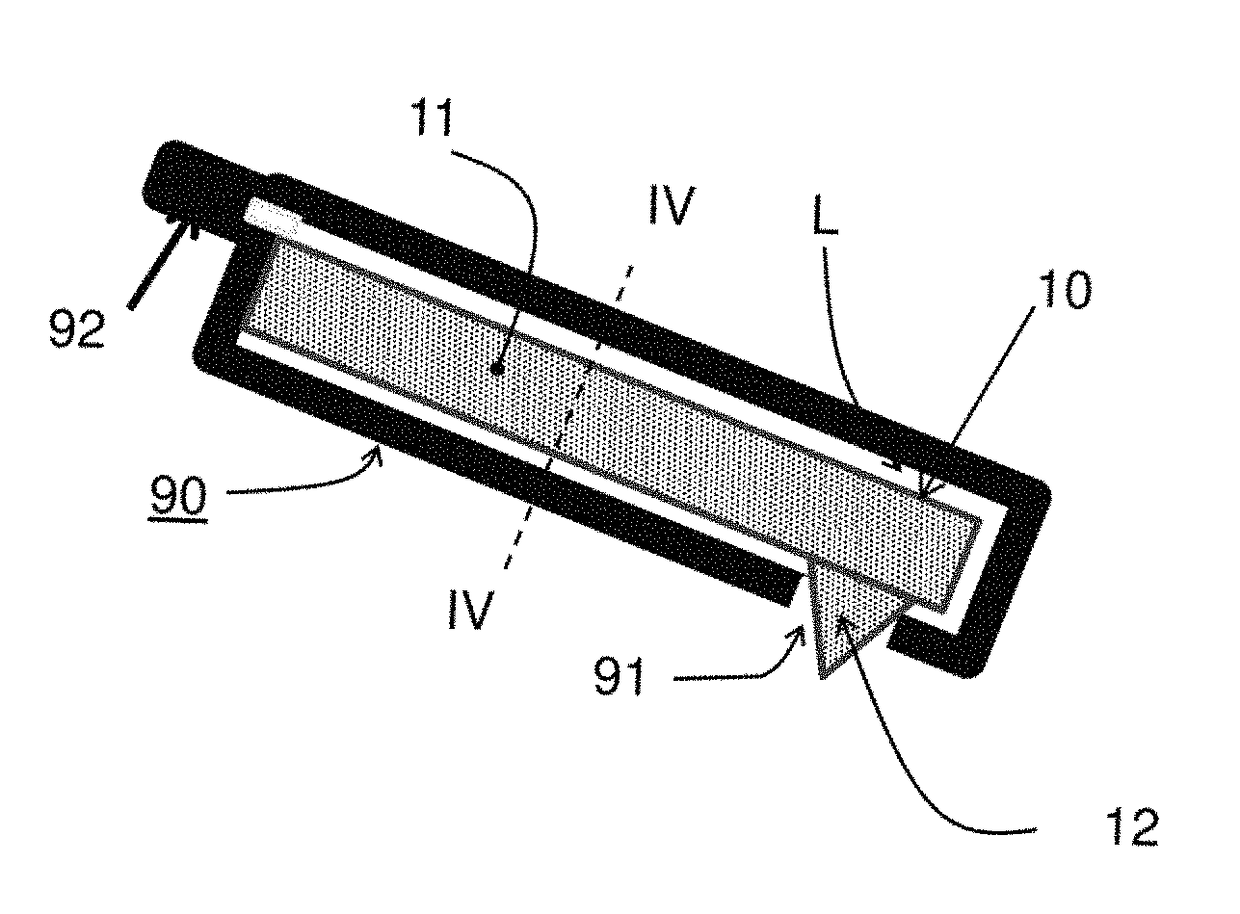
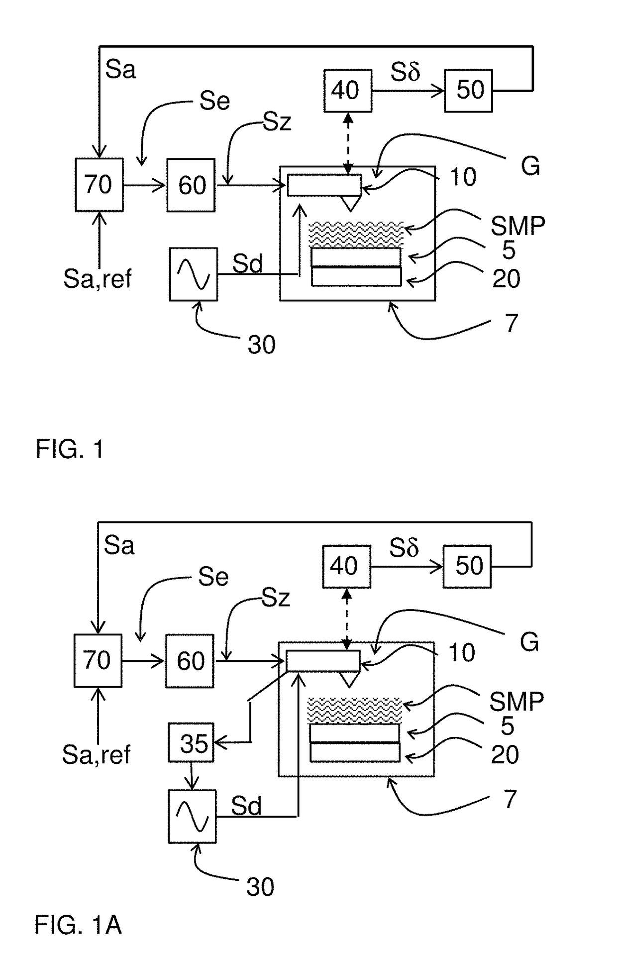
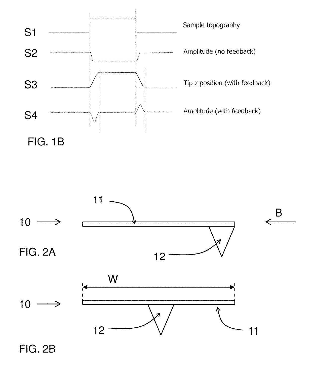
[0051]FIG. 1 schematically illustrates scanning probe microscope comprising a scanning probe 10 for scanning a sample SMP. In the embodiment shown the scanning probe 10 is formed as a cantilever 11 provided with a tip 12, as shown in FIG. 2A, 2B. Therein FIG. 2A shows a side view and FIG. 2B shows a front view of the scanning probe according to B in FIG. 2A. A holder 5 is provided for holding a sample SMP in an environment free from liquid. In the embodiment shown the sample SMP and the scanning probe are arranged in a housing 7 that can be filled with a gas G. A scanning arrangement 20 is provided for inducing a relative motion of the scanning probe 10 with respect to said sample SMP arranged on the holder 5. In this way the probe 10 can be scanned along a surface of the sample SMP. Various implementations are possible. The scanning arrangement 20 may keep the sample SMP stationar...


PUM


Abstract

A scanning probe microscope is provided comprising a scanning probe (10), a holder (5) for holding a sample (SMP) in an environment free from liquid. A scanning arrangement (20) is provided therein for inducing a relative motion of the scanning probe (10) with respect to said sample (SMP) along a surface of the sample (SMP). A driver (30) generates a drive signal (Sd) to induce an oscillating motion of the scanning probe (10) relative to the surface of the sample to be scanned. A measuring unit (40) measure a deflection of the scanning probe (10), and provides a deflection signal (Sδ) indicative for said deflection. An amplitude detector (50) detects an amplitude of the oscillating motion as indicated by the deflection signal (Sδ) and provides an amplitude signal (Sa) indicative for the amplitude. The scanning probe (10) is at least partly arranged in a liquid (L) to dampen motion of said scanning probe, and therewith has a quality factor Q which is less than or equal than 5. The scanning probe (10) is accommodated in a casing (90) comprising said liquid (L), the scanning probe (10) comprising a flexible carrier (11), the flexible carrier having a movable part provided with a tip (12), which tip (12) extends through an opening (91) in said casing.

Description

[0001]This application is the U.S. National Phase of, and Applicants claim priority from, International Patent Application Number PCT / NL2015 / 050699 filed 5 Oct. 2015, which claims priority from EP 14187831.4 filed 6 Oct. 2014, each of which is incorporated herein by reference.BACKGROUND OF THE INVENTION[0002]Field of the Invention[0003]The present invention relates to an scanning probe microscope. The present invention further relates to a method of operating an scanning probe microscope.[0004]Related Art[0005]Scanning probe microscopes (SPM), such as Atomic Force Microscopes (AFM) are widely used for the physical characterization of materials and devices when high spatial resolution and small feature sizes are of interest. AFMs are primarily used in imaging modes to provide topographic information, but they can also record the force between a probe tip and a sample. In AFM, the probe tip is typically positioned on a cantilever spring, which serves as a flexible carrier that transl...

Claims


Application Information

Patent Timeline
Patent Type & Authority Patents(United States)
IPC IPC(8): G01Q10/06G01Q70/04G01Q30/18
CPCG01Q30/18G01Q70/04G01Q30/12G01Q60/32
Inventor TABAK, FEMKE CHANTALSADEGHIAN MARNANI, HAMEDVAN ES, MAARTEN HUBERTUS
Owner NEDERLANDSE ORG VOOR TOEGEPAST NATUURWETENSCHAPPELIJK ONDERZOEK TNO
Why Eureka
Try Eureka