Shelving unit

a technology for shelving units and shelves, applied in the field of shelving units, can solve the problems of metal or rust stains on stored clothing and other valuable items, leave imprints on items, and are especially sever

Inactive Publication Date: 2002-11-07
GAWEL THEODORE E
View PDF0 Cites 8 Cited by
  • Summary
  • Abstract
  • Description
  • Claims
  • Application Information

AI Technical Summary

Problems solved by technology

Such racks have been found to have many disadvantages including the fact that because they are formed from spaced-apart wires, they leave imprints on items placed on the rack in contact with the wires.
This can be especially severe when the protective coating on the wires is broken and leaves metal or rust stains on stored clothing and other valuable items.
Although paper, cardboard, and heavier flexible vinyl, plastic, or rubber materials can be laid on the wire racks to prevent direct contact of stored items with the support wires, this presents a further problem in that such materials may pull forward when a selected item is removed from the rack causing the contents of the entire shelf to fall from the shelf doing possible damage to the stored items and causing possible injury to the nearby individual.
The inventor realizes that this is insufficient to prevent slippage and thus further treats the underside of his pad with an adhesive that adheres to the vinyl coating used with wire shelving.
Unfortunately the use of tackifying (sticky or adhesive-like) agents on the bottom of the pad bring with it additional problems.
First much of the tackifying agent will be exposed to the air in the area between the wire cross members and will tend to attract and accumulate dirt and dust.
Second, the tackifying agent may eventually dry and produce a bond between the soft pad and the cross-member wires.
Since the pad is of soft material, it is likely to tear and pull away from the wires leaving unsightly chunks of material attached to the wire-cross members when one attempts to move or remove the liner.
Even if the pad material does not become glued to the cross-members wires, some of the adhesive is likely to remain behind leaving the wires sticky and gummy.
Where the wires are sticky and gummy or have pieces of pad attached or both, they become virtually impossible to conveniently clean and restore to their original state.
Both U.S. Pat. No. 5,697,302 and U.S. Pat. No. 5,538,147 address the slippage problem but in a less than satisfactory manner.
As noted in the U.S. Pat. No. 5,697,302, such covers simply do not provide adequate support on a wire-frame shelf.
They are easily damaged and require frequent replacement.
It is further noted that because the material is thin and flexible, the tabs are unlikely to have much effect in preventing movement of the covers.
If the cover is produced from thicker material, manipulation of the tabs becomes a problem.
Less flexible material is likely to crack and break when the tab is bent into position.
Further the manipulation of the tab between the wire cross members and their subsequent movement to the interlock position is likely to be quite difficult for thicker cover materials.
This presents the problem of wear and possible chipping of the paint on the wire rack member during installation and use of the panel.
Generally it is noted that when any of the prior art devices must be attached to the wire rack, it may be inconvenient to manipulate the attaching devices on lower shelving, especially securing devices that must be manipulated from below the wire rack.
This can be especially troublesome for individuals with arthritic and other joint conditions who cannot stoop or bend to reach below lower level racks or manipulate the intricate securing devices.
Finally it is noted that none of the prior art devices have the ability to freshen the air, linens and clothing and / or repel moths and other insects.

Method used


Image

  • Shelving unit
  • Shelving unit
  • Shelving unit

Examples


Embodiment Construction

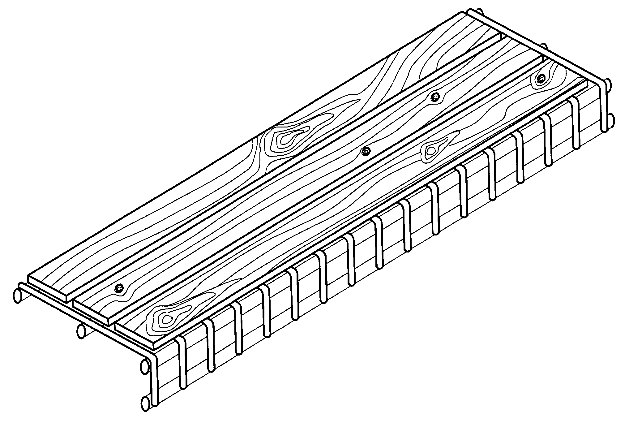
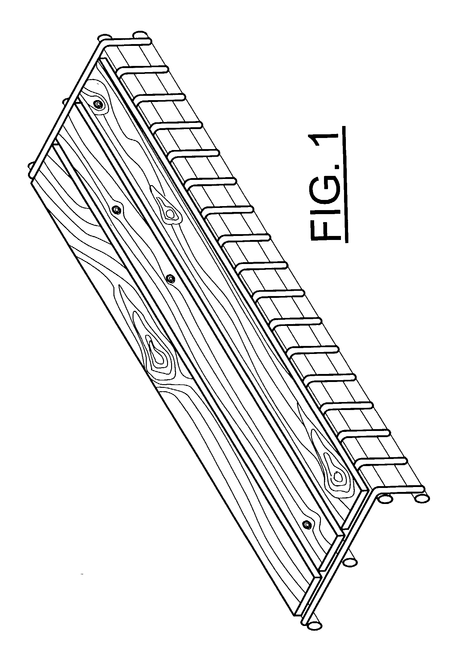
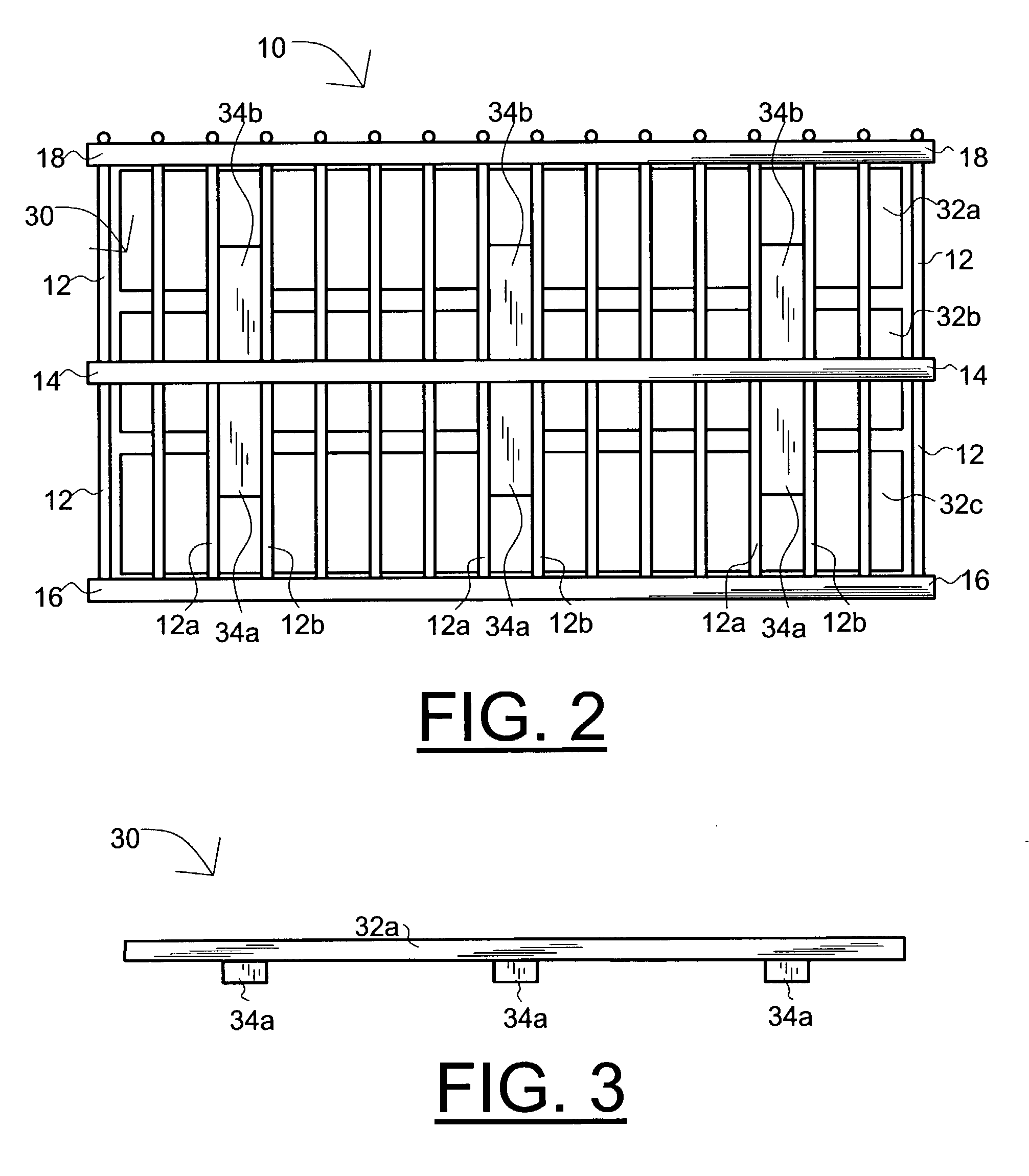
[0037] With reference to FIGS. 1-10, the shelving unit of the present invention is designated generally by the numeral 30. The wire rack with which it is configured to be used is designated by the numeral 10. As shown in the side view of FIG. 6, a simple wire rack 10 has a rear support rod 16 and a front support rod 24 joined by a plurality of coplanar transverse cross wires 12 to form a horizontal plane. The plurality of support wires can be seen in FIGS. 1 and 2. Various modifications to this basic design are made by different manufacturers to reinforce cross wires 12 and / or provide for attaching points for mounting hardware or for hanging clothing by means of cloths hangers.

[0038] In the wire rack shown in FIGS. 1, 2, and 4, the transverse cross wires 12 are bent downward around rod 24 to join a lower rod 18. In FIG. 5, the lower and upper rods 18, 24 are joined by post 26. In wire rack 10 of FIG. 6, the lower rod has been omitted completely.

[0039] Depending on the manufacturer, ...


PUM


Abstract

A shelving unit for a wire rack is formed from an essentially flat elongated shelf member with at least one cleat attached transverse to the underside of the shelf member and extending downward between a pair of adjacent support wires of the wire rack, preferably in a frictional fit to prevent movement of the shelf in a sideways, forward and back, or twisting manner. Additional cleats, spaced apart from each other and extending downward between other pairs of support wires are typically used. The shelf unit member may be formed from slats that are spaced apart from each other or in contact with each other in a butt, lap, tongue and grove or other joint arrangement. Each cleat may be formed as two or more spaced apart cleat sections that, when properly sized and positioned, accept differently positioned cental support rods from major wire-rack manufacturers which serve as a stop to prevent the shelf unit from falling from the wire rack. Preferably, the cleats and shelf member are made from aromatic cedar to give an air, linen and clothing freshening aroma and insect repelling qualities.

Description

[0001] This is a continuation of my prior application Ser. No. 09 / 566,115, filed May 5, 2000, now U.S. Pat. No. 6,401,945 which claims the benefit of U.S. Provisional Application No. 60 / 133,158 filed on May 7, 1999 all of which is incorporated by reference as if completely written herein.[0002] 1. Field of the Invention[0003] This invention pertains to shelving and more particularly to a shelving unit adapted for use with a wire rack.[0004] 2. Background of the Invention[0005] Wire racks have been a staple of the building industry as a quick and easy shelving device and are fully exemplified in several U.S. patents such as U.S. Pat. Nos. 4,316,593; 4,781,349; 5,148,928; and 5,346,077. Such racks have been found to have many disadvantages including the fact that because they are formed from spaced-apart wires, they leave imprints on items placed on the rack in contact with the wires. This can be especially severe when the protective coating on the wires is broken and leaves metal or ...

Claims


Application Information

Patent Timeline
Patent Type & Authority Applications(United States)
IPC IPC(8): A47B96/02A47F5/00
CPCA47F5/0043A47B96/021
Inventor GAWEL, THEODORE E.
Owner GAWEL THEODORE E
Why Eureka
Try Eureka