Mounting bracket for curtain rods

Inactive Publication Date: 2002-11-07
DOWNEY JOANNE +1
View PDF1 Cites 6 Cited by
  • Summary
  • Abstract
  • Description
  • Claims
  • Application Information

AI Technical Summary

Problems solved by technology

In this manner, lateral movement of the carriers, which causes opening and closing of the vertical blinds, likewise causes an opening and closing of the curtain.
None of the aforementioned prior art patents teach or disclose the features and stru

Method used


Image

  • Mounting bracket for curtain rods
  • Mounting bracket for curtain rods
  • Mounting bracket for curtain rods

Examples


first embodiment 10

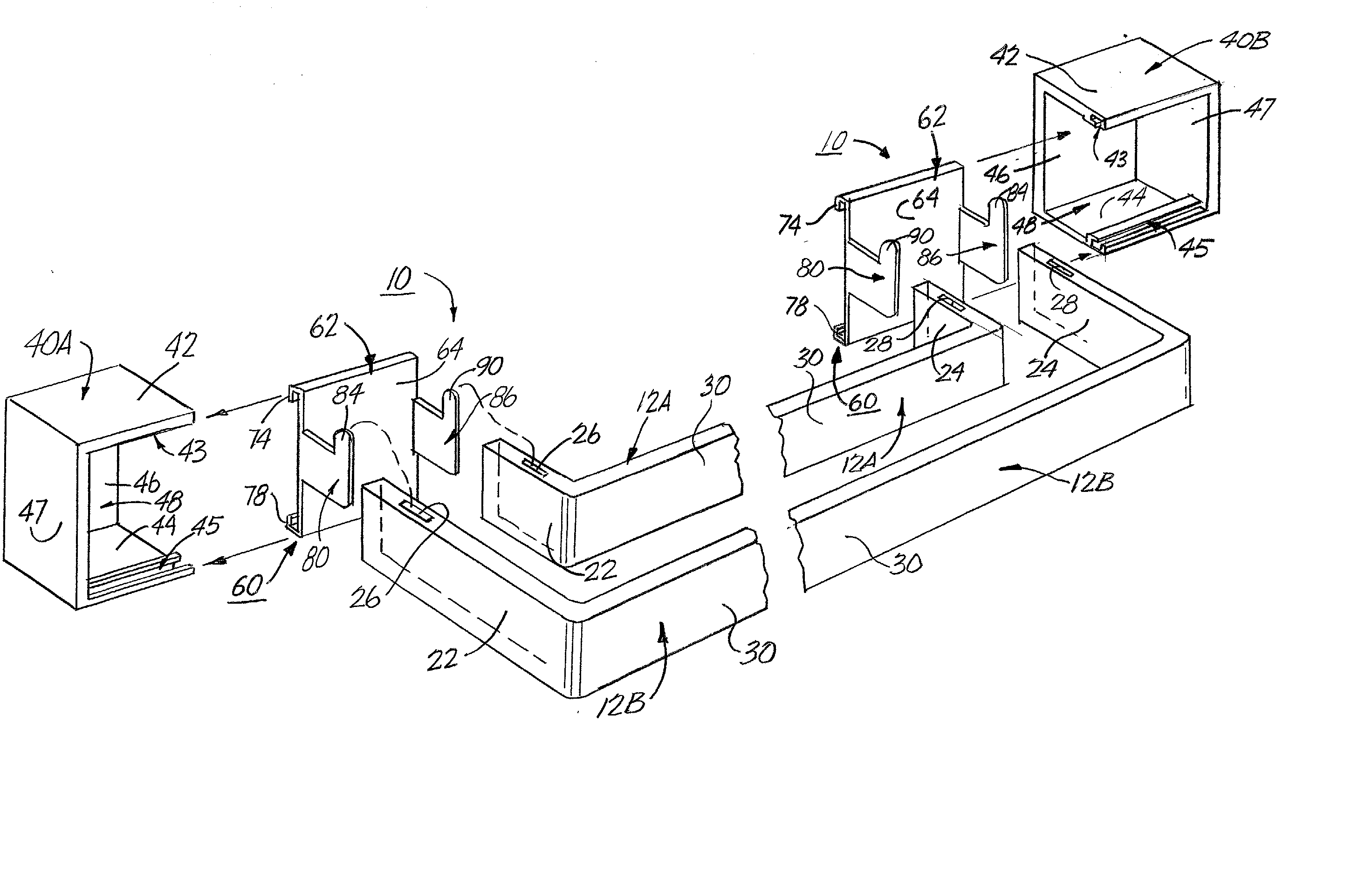
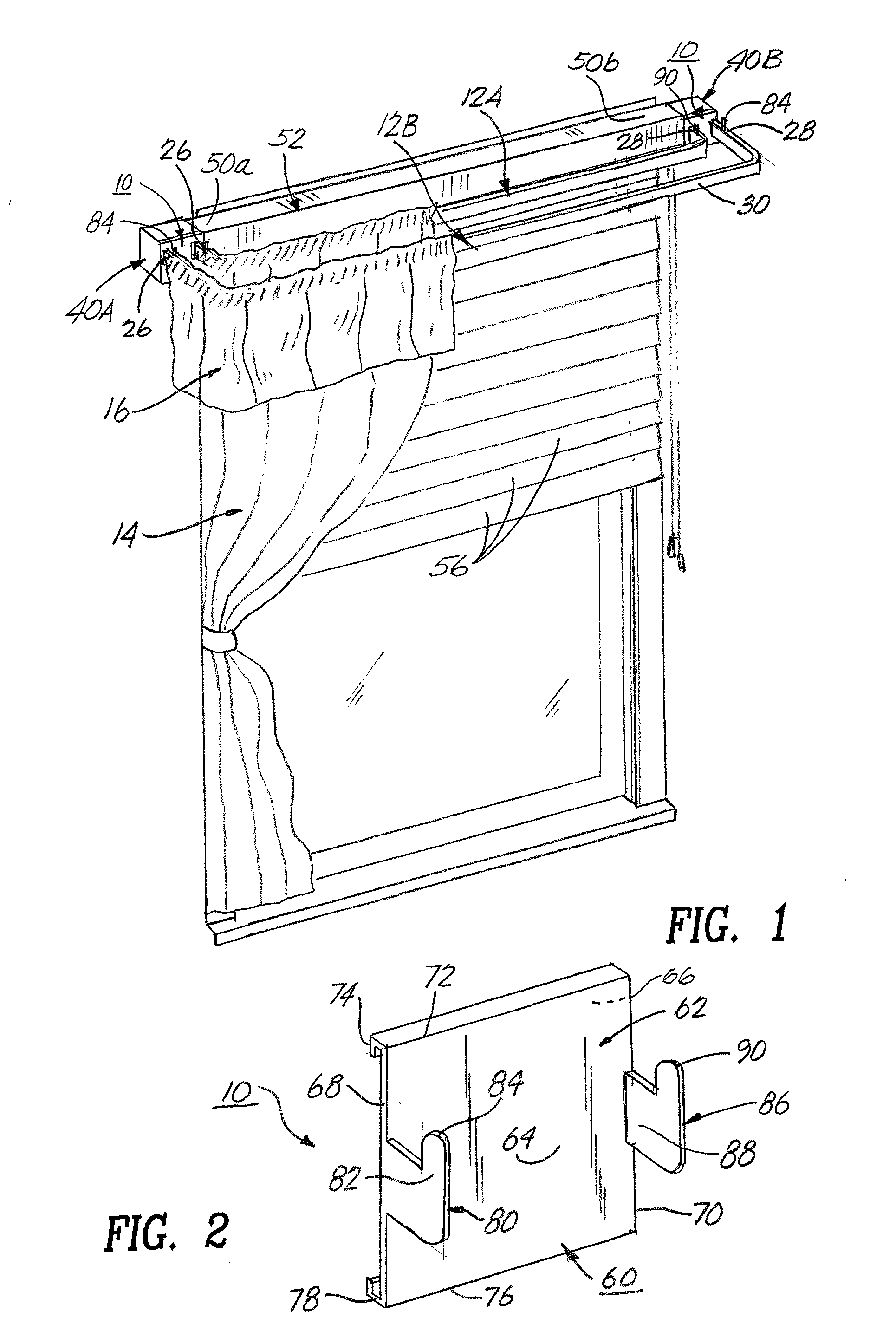
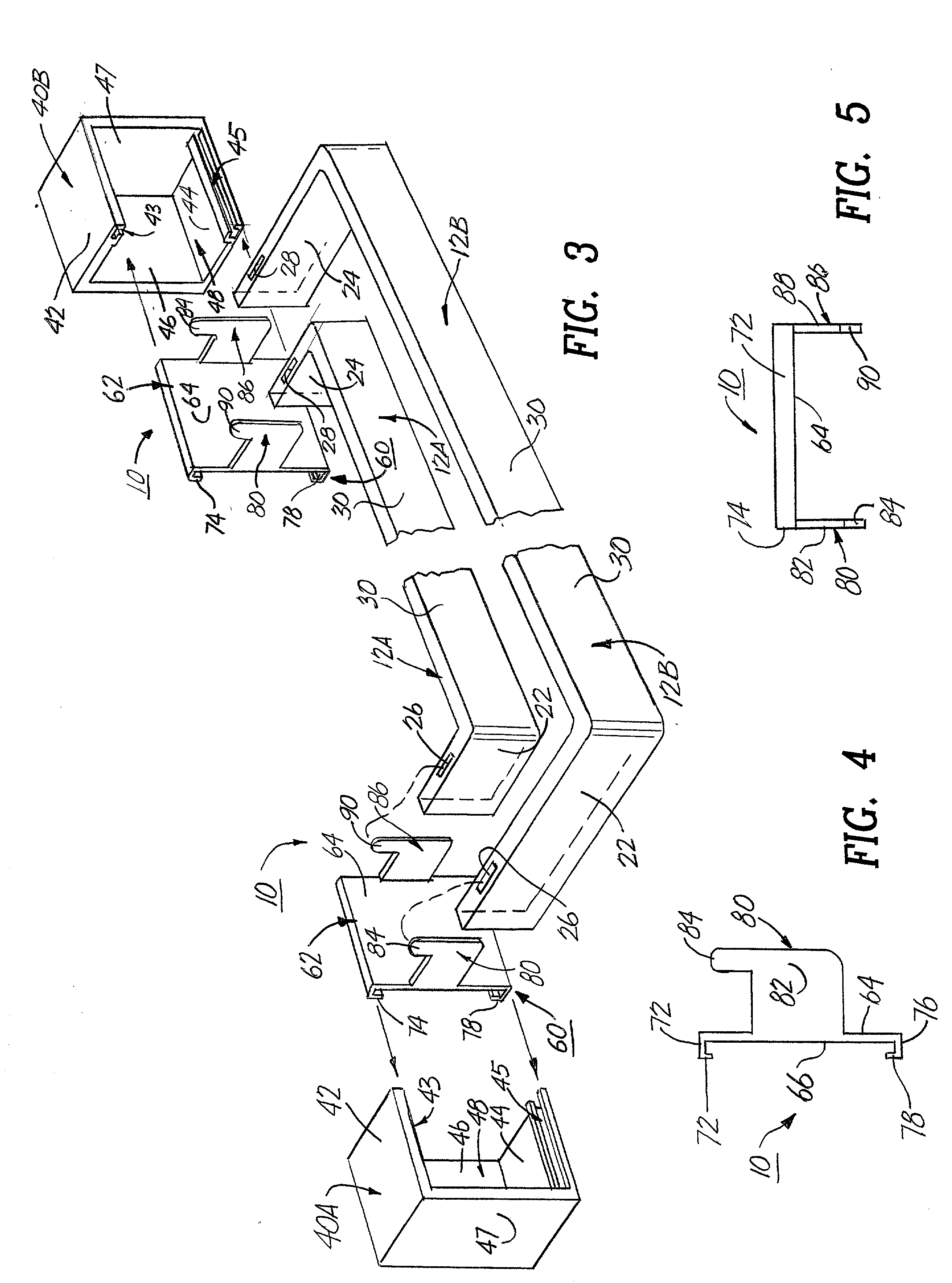
[0043] The curtain mounting bracket 10 and its component parts of the first embodiment of the present invention are represented in detail by FIGS. 1 through 5 of the patent drawings. The curtain mounting brackets 10 are used for attaching one or more standard flat curtain rods 12A and / or 12B in conjunction with a pair of blind bracket mounting devices 40A and 40B of a blind mounting assembly 52 having a plurality of horizontal blind members 56 thereon, such that the flat curtain rods 12A and 12B are used to hold a curtain 14 and a valance 16 thereon, as depicted in FIG. 1 of the drawings.

[0044] Each curtain mounting bracket 10 includes a bracket housing 60 having a holding wall member 62 and integrally connected outer and inner holding prong member 80 and 86 thereon, as depicted in FIGS. 2 and 3 of the drawings. Holding wall member 62 includes a front wall surface 64, a rear wall surface 66, left and right side perimeter edges 68 and 70, an upper perimeter edge 72 having an upper L-...

second embodiment 100

[0045] The curtain mounting bracket 100 and its component parts of the second embodiment of the present invention are represented in detail by FIGS. 6 through 10 of the patent drawings. The curtain mounting brackets 100 are used for attaching a single standard cylindrical curtain rod 32a in conjunction with a pair of blind bracket mounting devices 40A and 40B of a blind mounting assembly 52 having a plurality of vertical blind members 54 thereon, such that the single cylindrical curtain rod 32A is used to hold a curtain 14 or a valance 16 thereon, as depicted in FIG. 6 of the drawings.

[0046] Each curtain mounting bracket 100 includes a bracket housing 120 having a holding wall member 122 and an integrally attached holding arm member 140 with a rod holding section 142 thereon, as depicted in FIGS. 7 and 8 of the drawings. Holding wall member 122 includes a front wall surface 124, a rear wall surface 126, an upper perimeter edge 128 having an upper L-shaped retaining tab member 130 th...

third embodiment 200

[0047] The curtain mounting bracket 200 and its component parts of the third embodiment of the present invention are represented in detail by FIGS. 11 through 15 of the patent drawings. The curtain mounting brackets 200 are used for attaching one or more standard cylindrical curtain rods standard cylindrical curtain rods 32A and / or 32B in conjunction with a pair of blind bracket mounting devices 40A and 40B of blind mounting assembly 52 having a plurality of vertical blind members 54 thereon, such that the cylindrical curtain rods 32A and 32B are used to hold a curtain 14 and a valance 16 thereon, as shown in FIG. 11 of the drawings.

[0048] Each curtain mounting bracket 200 includes a bracket housing 220 having a holding wall member 222 and an integrally attached holding arm member 240 with inner and outer rod holding sections 242 and 244 thereon, as depicted in FIGS. 12 and 13 of the drawings. Holding wall member 222 includes a front wall surface 224, a rear wall surface 226, an upp...


PUM


Abstract

Curtain mounting brackets for curtain rods for use with conventional blind bracket mounting devices of a blind assembly for attaching one or more curtain rods thereon in order to hold a curtain and/or valance thereto. The curtain mounting brackets include a first bracket housing having a first holding wall member with an upper first perimeter edge with an upper first L-shaped retaining tab member thereon, a lower first perimeter edge with a lower first L-shaped retaining tab member thereon, a first side perimeter edge and a second side perimeter edge; the first holding wall member includes an integrally connected first curtain rod holding element thereon; and the upper first L-shaped retaining tab member of the first holding wall member for engaging and being joined to an upper receiving channel of the conventional blind bracket mounting device, and the lower L-shaped retaining tab member of the first holding wall member for engaging and being joined to a lower receiving channel of the conventional blind bracket mounting device for preventing one end of the blind assembly from falling out of the blind bracket mounting device. The curtain mounting brackets also include a second bracket housing having a second holding wall member with an upper second perimeter edge with an upper second L-shaped retaining tab member thereon, a lower second perimeter edge with a lower second L-shaped retaining tab member thereon, a third side perimeter edge and a fourth side perimeter edge; the second holding wall member includes an integrally connected second curtain rod holding element thereon; and the upper second L-shaped retaining tab member of second holding wall member for engaging and being joined to an upper receiving channel of the conventional blind bracket mounting device, and lower second L-shaped retaining tab member of the second holding wall member for engaging and being joined to a lower receiving channel of the conventional blind bracket mounting device for preventing the other end of the blind assembly from falling out of the blind bracket mounting device. The first and second curtain rod holding elements of the first and second holding wall members are used for receiving one or more curtain rods thereon.

Description

[0001] The invention relates to a mounting bracket for use in attaching curtain rods in conjunction with a standard blind bracket mounting device of a blind assembly. More particularly, the mounting bracket is slidably mounted on the blind assembly and prevents the blind assembly form falling out of the blind bracket mounting device.[0002] Mounting brackets of various designs have been used to support shades, blinds, curtains, valances, cornices and the like. These brackets are mounted or fastened to a wall, or to a window frame or to a blind apparatus in a number of various positions depending upon the structure of the mounting bracket and / or hanging element (i.e. curtain). Conventional designs for these mounting brackets include channel-type, metal headrails; box-like metal structures having a plurality of slide plates therein; U-shaped metal structures having a screw clamp; an L-shaped metal flange having a snap holder; an inverted L-shaped metal stamping having horizontal and ve...

Claims


Application Information

Patent Timeline
IPC IPC(8): A47H1/14
CPCA47H2001/021A47H1/14
Inventor DOWNEY, JOANNEMCMENAMIN, TIM SR.
Owner DOWNEY JOANNE
Why Eureka
Try Eureka