Window and sliding glass door having push button locking mechanism

Inactive Publication Date: 2004-03-23
MICHAEL ALEXANDER
View PDF8 Cites 14 Cited by
  • Summary
  • Abstract
  • Description
  • Claims
  • Application Information

AI Technical Summary

Problems solved by technology

This prior art patent does not teach or disclose the particular structure of a sliding door push button locking mechanism that uses a rocker lever arm for inserting or retracting a locking pin in order to allow the two windows or two glass sliding doors to be opened or closed.
These prior art patents do not teach or disclose the particular structure of a sliding door push button locking mechanism that uses a rocker leve

Method used


Image

  • Window and sliding glass door having push button locking mechanism
  • Window and sliding glass door having push button locking mechanism
  • Window and sliding glass door having push button locking mechanism

Examples


embodiment 10

Preferred Embodiment 10

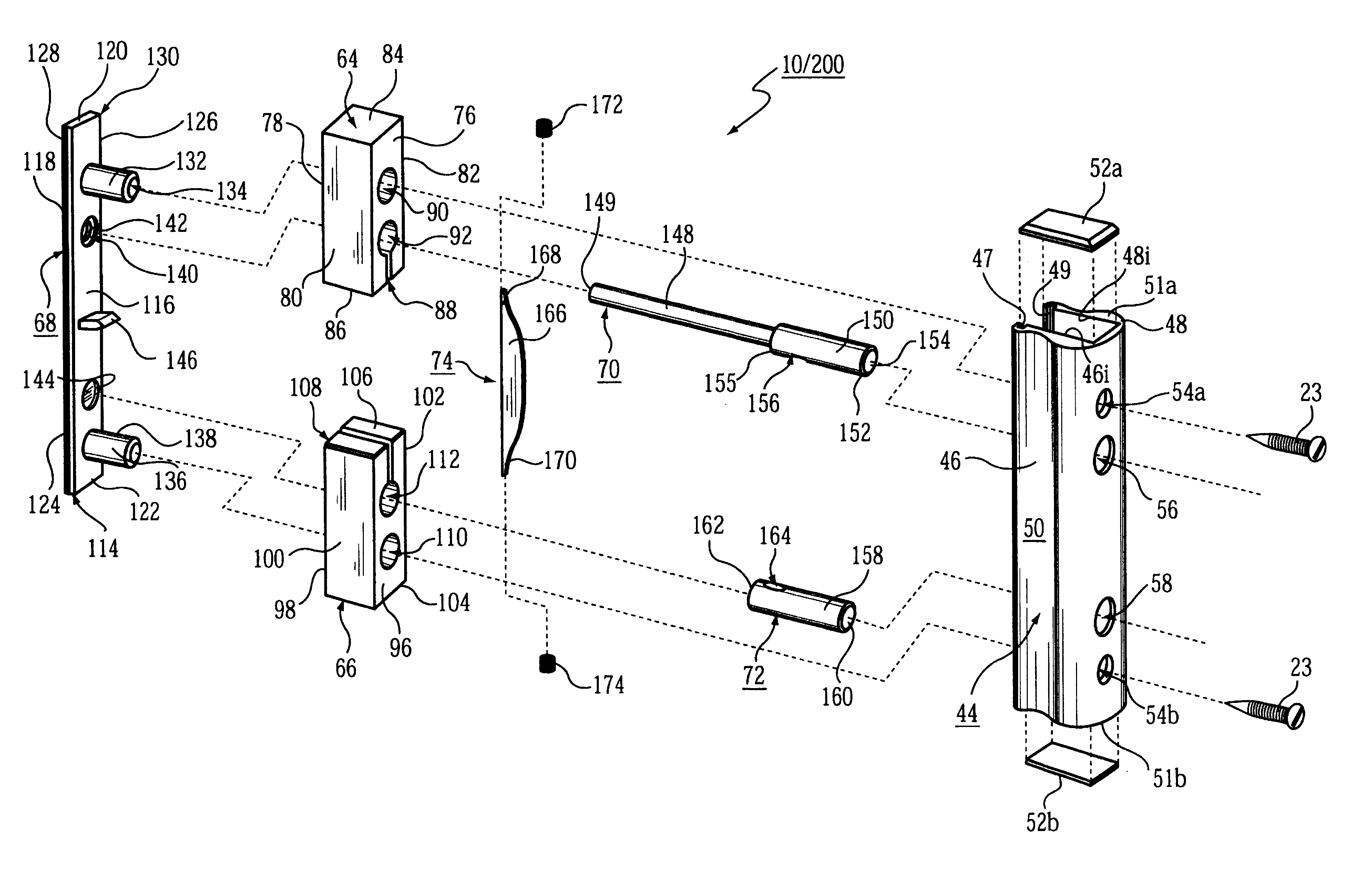
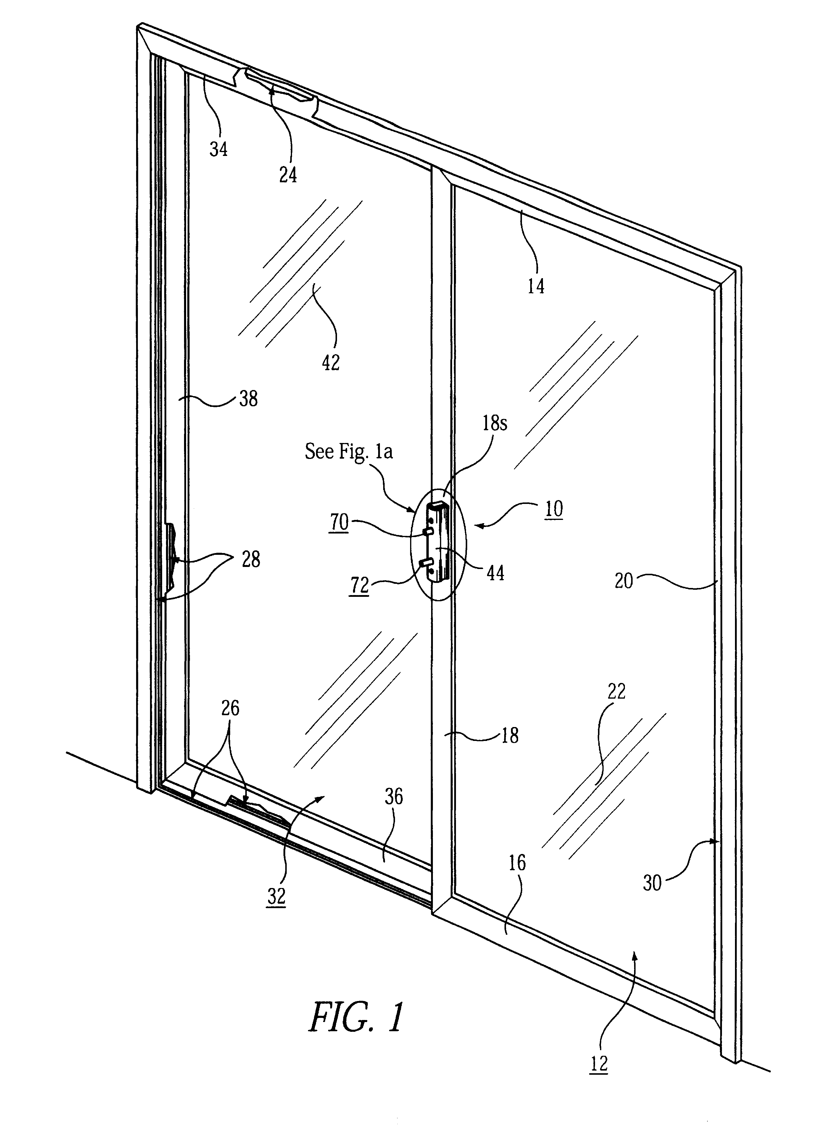
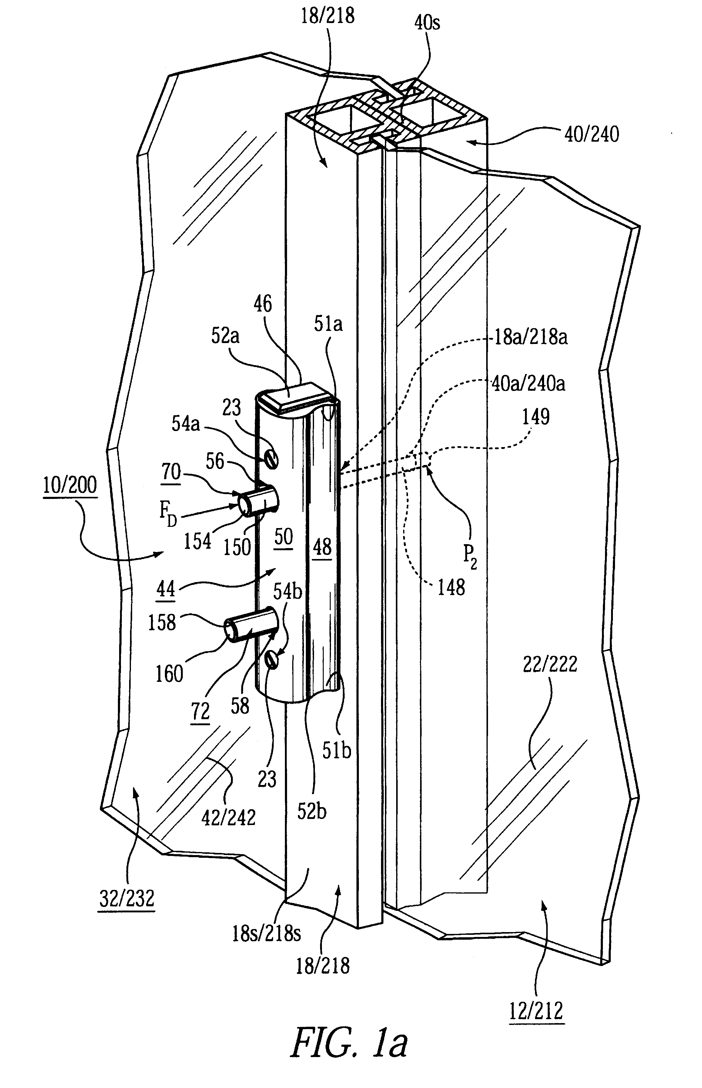
A sliding door locking mechanism 10 having an integral push button locking assembly 60 is represented in detail by FIGS. 1 through 7 of the patent drawings. The sliding door locking mechanism 10 is used in conjunction with a pair of sliding glass doors / panels 12 and 32 being mounted between upper and lower sliding tracks 24 and 26; and opposing (vertical) side tracks 28 and 30. The first sliding glass panel 12, as shown in FIG. 1, includes an upper rail 14, a lower rail 16, and vertical stiles 18 and 20 for enclosing a glass window 22 therein. The second sliding glass panel 32, as shown in FIG. 1, includes an upper rail 34, a lower rail 36, and vertical stiles 38 and 40 for enclosing a glass window 42 therein. The sliding door locking mechanism 10 is centrally mounted on the inner vertical stile 18 of the first sliding glass panel 12, as shown in FIG. 1a. The outer wall surface 18s of inner vertical stile 18 includes mounting openings 19a and 19b for receiving...

embodiment 200

Alternate Embodiment 200

In an alternate embodiment, a window locking mechanism 200 has an integral push button locking assembly 60 which is represented in detail by FIGS. 1a, 1b, 2, 3, 8 and 9 of the patent drawings. As shown in FIG. 8, the window locking mechanism 200 is used in conjunction with a pair of sliding glass windows 212 and 232 being mounted between upper and lower sliding tracks 224 and 226; and opposing (vertical) side tracks 228 and 230. Alternatively, the windows may move vertically, as shown in FIG. 9, using the window locking mechanism 200. The first sliding glass window panel 212, as shown in FIG. 8, includes an upper rail 214, a lower rail 216, and vertical stiles 218 and 220 for enclosing a glass window 222 therein. The second sliding glass window panel 232, as shown in FIG. 8, includes an upper rail 234, a lower rail 236, and vertical stiles 238 and 240 for enclosing a glass window 242 therein. The sliding window locking mechanism 200 is centrally mounted on th...


PUM


Abstract

A window locking mechanism or sliding door locking mechanism includes a cover having an internal compartment for receiving a push button locking assembly therein. The push button locking assembly includes a rocker lever arm sub-assembly, a locking pin, a releasing pin and a push button housing all connected together. The rocker lever arm sub-assembly includes a lever arm having a tensioning spring mounted on each outer end. The rocker lever arm sub-assembly is movable between a locking position and an unlocking position for activating the releasing pin to withdraw the locking pin from the push button housing in order to allow a pair of windows or sliding doors to be unlocked, and for activating the locking pin for insertion of the locking pin in the push button housing in order to lock a pair of windows or sliding doors in a locked position.

Description

The present invention relates to an improved window or sliding glass door having an integral push button locking mechanism. More particularly, the locking mechanism includes a rocker lever arm for inserting or retracting a locking pin in order to allow the two windows or two glass sliding doors to be locked or unlocked accordingly.Sliding doors and windows are often locked by complex locking mechanisms that comprise many internal moving parts and thus are subject to disrepair. Also, the frame of the windows or doors are not of a sufficient size to receive large and secure locking mechanisms. Therefore, there is a need for a mechanism to lock the windows or lock the sliding glass doors that is secure, ergonomically efficient, simple to use, and requires only a minimal number of internal moving parts to withstand everyday wear and tear.DESCRIPTION OF THE PRIOR ARTSliding door locks, plug-in locks, slidable door safety locks, window locking devices sliding closure locking devices, slid...

Claims


Application Information

Patent Timeline
IPC IPC(8): E05B65/08E05B65/00E05C7/00
CPCE05B65/0864E05B65/0025E05C2007/007Y10S292/37Y10T292/1014
Inventor MICHAEL, ALEXANDER
Owner MICHAEL ALEXANDER
Why Eureka
Try Eureka